


THEORY OF OPERATION
E-3 E-3
INVERTEC® V155-S
Return to Section TOC Return to Section TOC Return to Section TOC Return to Section TOC
Return to Master TOC Return to Master TOC Return to Master TOC Return to Master TOC
INPUT BOARD
The Input Board includes the following circuits:
- Automatic Reconnect Circuit: This circuit monitors
the input voltage and automatically reconnects the
inverter and auxiliary connections to configure the
machine for either 115V or 230V ac input voltage. The
proper configuration is achieved through the use of
board mounted relays. These relays and others that
activate the Pre-charge circuitry and the fan circuit
are controlled through signals from a micro-processor
on the board.
- Switching Power Supply: Supplied by a board
mounted transformer, the switching power supply
provides +15 vdc and +5vdc supplies for use on all of
the PC Boards.
- Input Rectifier and Precharge Circuit: The Pre-
charge rectifier and current limiting resistors apply a
small charge to the filter capacitors when the Power
Switch is turned ON.
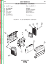
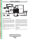
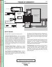
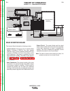
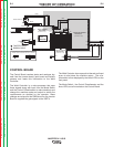
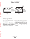
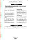
FIGURE E.3 — INPUT BOARD
An improper input voltage would be recognized dur-
ing this time and an input error sent to the Control
Board. A signal from the Control Board would prevent
further power-up to prevent damage to the Inverter
Board.
- The re-connect relays then apply full power from the
input line (AC1 and AC2) to the Input Rectifier and the
capacitors are fully charged to approximately
325VDC. (See the Machine Diagram and PC Board
Schematics for more information).
- Auto Reset Fuse: A self reseting fuse circuit (ARFU)
on the Input Board helps to prevent damage to the
machine from over-current when in 120VAC opera-
tion. When the fuse is open, the output will be dis-
abled and the yellow Temperature LED on the front
panel will be ON.
NOTE: Unshaded areas of Block Logic
Diagram are the subject of discussion
CONTROL
BOARD
W
0
5
X
0
7
0
8
-1
(
S
CHE
MA
T
IC: X
0
7
0
8
)
J
P1
I
N
P
U
T
B
OA
R
D
W
0
5
X
0
7
0
1
(
S
C
H
E
M
A
T
I
C
:
X
0
7
0
1
)
1
1
5
/
2
3
0
V
a
c
5
0
/6
0
Hz
ON
/
OFF
S
W
I
TC
H
5
2
N
L
G
W
IRE
T
IE
4
1
B
L
U
E
W
H
I
T
E
W
H
I
T
E
B
L
U
E
W
H
I
T
E
B
LA
C
K
A
C2
A
C
1
P
E
P
W
R
2
P
W
R
1
PW
R
4
P
W
R
3
D
C
+
R
ED
D
C
-
B
LA
C
K
P
C
B
C
ON
N
E
C
TOR
C
A
V
I
TY
N
U
M
B
E
R
I
N
G S
E
QU
E
N
C
E
(
V
I
E
WE
D F
RO
M
CO
M
P
O
NE
NT
S
I
DE
O
F
P
.
C.
B
O
A
RD)
R
I
BBO
N
C
ABLE
T
WI
S
T
E
D
C
A
B
L
E
1
F
A
N
W
H
I
T
E
R
E
D
4
2
4
PIN
S
1
P
E
R
E
C
O
N
N
E
C
T
B
O
A
R
D
W
05X
0408
(
S
C
H
E
M
A
T
I
C
:
X
0
4
0
8
)
B
LA
C
K
J
P
4
B
L
U
E
1
6
1
6
PI
NS
15
JP
1
J
P1
D
C
+
R
ED
D
C
-
B
LA
C
K
Y
/G
P
E
I
N
V
E
R
T
E
R
B
O
A
R
D
W05X
0519
(
S
C
H
E
M
A
T
IC
:
X
0
5
1
9
)
BLAC
K
R
ED
J
P
2
W
HITE
WHITE
P
1
N1
BLACK
RED
S
H
U
N
T
-
+