


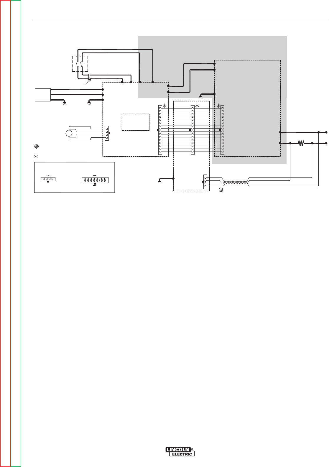
THEORY OF OPERATION
E-5 E-5
INVERTEC® V155-S
Return to Section TOC Return to Section TOC Return to Section TOC Return to Section TOC
Return to Master TOC Return to Master TOC Return to Master TOC Return to Master TOC
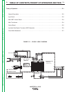
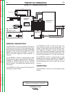
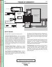
CONTROL BOARD
The Control Board receives status and analogue sig-
nals from the inverter board, input board and various
sensors and feeds this information to the Weld
Controller.
The Weld Controller is a micro-processor that uses
these signals along with input from the Mode Switch
and the Control Potentiometer to make decisions and
change the machine mode and output to satisfy the
requirements as decided by the operator. these
changes are relayed to the PWM circuit on the Inverter
Board to regulate the gate signals to the IGBT”s
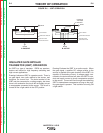
FIGURE E.5 — CONTROL BOARD
The Weld Controler also responds to thermal and input
errors to shut down the machine output. The error
information is then displayed by the three LEDʼs on the
front panel.
The Mode Switch , the Control Potentiometer and the
three LEDʼs are all mounted on the Control Board.
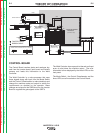
CONTROL
BOARD
W
0
5
X
0
7
0
8
-1
(
S
CHE
MA
T
IC: X
0
7
0
8
)
J
P1
I
N
P
U
T
B
OA
R
D
W
0
5
X
0
7
0
1
(
S
C
H
E
M
A
T
I
C
:
X
0
7
0
1
)
1
1
5
/
2
3
0
V
a
c
5
0
/6
0
Hz
ON
/
OFF
S
W
I
TC
H
5
2
N
L
G
W
IRE
T
IE
4
1
B
L
U
E
W
H
I
T
E
W
H
I
T
E
B
L
U
E
W
H
I
T
E
B
LA
C
K
A
C2
A
C
1
P
E
P
W
R
2
P
W
R
1
PW
R
4
P
W
R
3
D
C
+
R
ED
D
C
-
B
LA
C
K
P
C
B
C
ON
N
E
C
TOR
C
A
V
I
TY
N
U
M
B
E
R
I
N
G S
E
QU
E
N
C
E
(
V
I
E
WE
D F
RO
M
CO
M
P
O
NE
NT
S
I
DE
O
F
P
.
C.
B
O
A
RD)
R
I
BBO
N
C
ABLE
T
WI
S
T
E
D
C
A
B
L
E
1
F
A
N
W
H
I
T
E
R
E
D
4
2
4
PIN
S
1
P
E
R
E
C
O
N
N
E
C
T
B
O
A
R
D
W
05X
0408
(
S
C
H
E
M
A
T
I
C
:
X
0
4
0
8
)
B
LA
C
K
J
P
4
B
L
U
E
1
6
1
6
PI
NS
15
JP
1
J
P1
D
C
+
R
ED
D
C
-
B
LA
C
K
Y
/G
P
E
I
N
V
E
R
T
E
R
B
O
A
R
D
W05X
0519
(
S
C
H
E
M
A
T
IC
:
X
0
5
1
9
)
BLAC
K
R
ED
J
P
2
W
HITE
WHITE
P
1
N1
BLACK
RED
S
H
U
N
T
-
+