


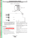


DC+
DC-
INPUT BOARD
AC2
AC1
JP1
PIN 2
PIN 1
15
1
3
11
9
7
5
3
16
1
4
12
10
8
6
4
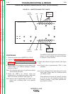
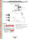
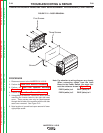
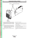
FIGURE F.10 – PLUG JP1 TESTPOINTS
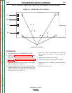
INVERTER BOARD VOLTAGE TEST (CONTINUED)
NOTE: DUE TO SAFETY REASONS AND THE PHYS-
ICAL LOCATION OF THE INVERTER, IT IS
NOT EASY TO PERFORM THE VOLTAGE
TEST AT THE INVERTER BOARD. CHECKS
CAN BE DONE AT THE INPUT BOARD CON-
NECTOR JP1. See Fig. F.10.
PROCEDURE
1. Disconnect power to the INVERTEC® V155-S.
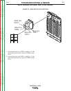
2. Perform the Case Cover Removal Procedure (left
side only).
3. Connect the main 230VAC to the machine and
switch ON the input switch.
4. Set the machine to STICK mode.
5. Locate the JP1 connector points. See figure F.10.
6. Using pins 8,9,16 or 15 as a common (-) ground:
Check pin 1-> +15VDC means fan is ON. 0VDC
means fan is OFF.
Check pin 3-> 0VDC during OCV condition.
Check pin 5-> +11.6VDC means the inverter is ON
(the first 5 minutes after activity) while 1.5VDC
means the inverter is OFF.
Check pin 6-> value changes from 7.6 to 8.5VDC
during reading when the inverter is ON. 50-60
mVDC when the inverter is OFF.
Check pin 7-> +15VDC.
Check pin 11-> +5VDC.
Check pin 12-> +5VDC (supply voltage generated
on input board).
Check pin 14-> +15VDC (supply voltage generat-
ed on input board).
7. Check to see if the correct microcontroller program
is preset: H490000005-004X where X is the revi-
sion number.
TROUBLESHOOTING & REPAIR
F-24 F-24
INVERTEC® V155-S
Return to Section TOC Return to Section TOC Return to Section TOC Return to Section TOC
Return to Master TOC Return to Master TOC Return to Master TOC Return to Master TOC