


I
N
V
E
R
T
E
C
V
1
5
5
Five Screws
I
n
v
e
t
e
r
B
o
a
r
d
Three Screws
Ground
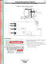
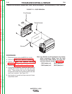
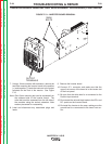
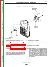
FIGURE F.12 – DOOR REMOVAL
INVERTER BOARD REMOVAL AND REPLACEMENT PROCEDURE (CONTINUED)
PROCEDURE
1. Disconnect power to the INVERTEC® V155-S.
2. Perform the Case Cover Removal Procedure.
3. Perform the Input Filter Capacitor Discharge
Procedure.
4. Perform the Input Board Removal Procedure.
5. Using phillips screwdriver, remove the three screws
mounting the inverter board to the right side case
cover. These screws can only be seen/accesed
through the left side of the machine with the left side
case cover removed. See Figure F.12.
6. Note location of ground lead upon removal of lower
right phillips screw.
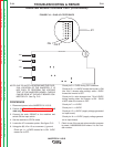
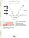
Note: Pay attention to wiring diagram very closely.
When connecting cables from the Input
Board to the Power Switch. You must con-
nect the cables as shown in Figure F.9.
PWR 2(white) to 4 PWR 1(blue) to 1
PWR 4(white) to 5 PWR 3(blue) to 2
TROUBLESHOOTING & REPAIR
F-28 F-28
INVERTEC® V155-S
Return to Section TOC Return to Section TOC Return to Section TOC Return to Section TOC
Return to Master TOC Return to Master TOC Return to Master TOC Return to Master TOC