


INSTALLATION
A-4 A-4
INVERTEC® V155-S
Return to Section TOC Return to Section TOC Return to Section TOC Return to Section TOC
Return to Master TOC Return to Master TOC Return to Master TOC Return to Master TOC
INPUT POWER CONNECTION
Check the input voltage, phase, and frequency sup-
plied to this machine before turning it on.
The allowable input voltage is indicated in the techni-
cal specification section of this manual and on the rat-
ing plate of the machine. Be sure that the machine is
grounded.
Make sure the power available at the input connection
is adequate for normal operation of the machine. The
fuse rating and cable sizes are both indicated in the
technical specification section of this manual.
Fuse the input circuit with time delay fuses marked “D”
or delay type
1
circuit breakers. Using fuses or circuit
breakers smaller than recommended may result in
“nuisance” shut-offs from welder inrush currents even
if not welding at high currents.
1
Also called “inverse time” or “thermal/magnetic” circuit breakers.
These circuit breakers have a delay in tripping action that decreases
as the magnitude of the current increases.
The INVERTEC® V155-S is recommended for use on
an individual branch circuit.
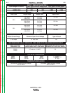
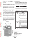
120V INPUT
The rated output of the INVERTEC® V155-S is avail-
able when connected to a 30A branch circuit. When
connected to a branch circuit with lower ampacity,
lower welding current and duty cycle must be used. An
output guide is provided below. The values are approx-
imate and must be adjusted downward if the fuse or
circuit breaker trips off. Other loads on the circuit and
fuse/circuit breaker characteristics will affect the avail-
able output. Do not exceed these welding conditions:
(See Table A.1)
The INVERTEC® V155-S is provided with a 120/230V
cable, 6.6ft.(2m) in length, with a 15Amp 5-15P plug
molded onto the cord.
The INVERTEC® V155-S is supplied with an addition-
al 20A plug that can replace the 15A plug to achieve
higher output. To install the supplied 20A plug:
Connect the white (neutral) wire under terminal clamp
with silver screw, and black (hot) wire under terminal
clamp with brass screw. Connect green wire under ter-
minal clamp with green screw.
•
Failure to wire as instructed may cause personal
injury or damage to equipment. To be installed or
checked by an electrician or qualified person
only.
---------------------------------------------------------------------------
230V INPUT
To achieve the full output capacity of the INVERTEC®
V155-S, 230VAC inputs should be used. The change
over is accomplished by replacing the 120VAC plug
with a 30 Amp 230VAC plug (NEMA 6-30P).
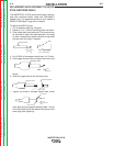
ATTACHMENT PLUG
In all cases, the green or green/yellow grounding wire
must be connected to the grounding pin of the plug, usu-
ally identified by a green screw.
All attachment plugs must comply with the Standard for
Attachment Plugs and Receptacles, UL498.
The product is considered acceptable for use only when
an attachment plug as specified is properly attached to
the supply cord.
The INVERTEC® V155-S will auto reconnect to either
120V or 230V supplies.
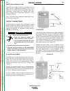
ENGINE DRIVEN GENERATOR
The machine is designed to operate on engine driven
generators as long as the auxiliary can supply ade-
quate voltage, frequency and power as indicated in the
"Technical Specification" Installation Section of this
manual. The auxiliary supply of the generator must
also meet the following conditions:
• Vac peak voltage: below 205V (for 115Vac input) or
410V (for 230Vac input).
• Vac frequency: in the range of 50 or 60 Hertz.
• RMS voltage of the AC waveform: 115Vac or
230Vac ± 10%
It is important to check these conditions because many
engine driven generators produce high voltage spikes.
Operation of this machine with engine driven genera-
tors not conforming to these conditions is not recom-
mended and may damage the machine.
WARNING
BRANCH
Plug
Rating
15 Amp
15 Amp
20 Amp
Branch
Rating
15 Amp
20 Amp
20 Amp
10% Duty
Cycle
65A
75A
85A
30% Duty
Cycle
55A
70A
75A
100% Duty
Cycle
45A
60A
60A
10% Duty
Cycle
100A
110A
130A
30% Duty
Cycle
85A
100A
130A
100% Duty
Cycle
75A
95A
95A
120V Input
Stick
TIG
Output Current
TABLE A.1