


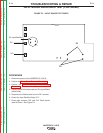
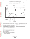
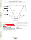

White from
PWR 2
White from
PWR4
Blue from
PWR 1
Blue from
PWR 3
3
1
2
6
4
5
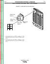
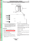
FIGURE F.9 – MAIN SWITCH PLUG LOCATION
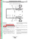
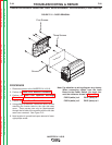
INPUT BOARD VOLTAGE TEST (CONTINUED)
1. Put the blue wire from PWR3 in position 2 of the
main switch while the white wire from PWR4 in posi-
tion 5.
2. Put the blue wire from PWR1 in position 1 of the
main switch while the white wire from PWR2 in posi-
tion 4.
TROUBLESHOOTING & REPAIR
F-21 F-21
INVERTEC® V155-S
Return to Section TOC Return to Section TOC Return to Section TOC Return to Section TOC
Return to Master TOC Return to Master TOC Return to Master TOC Return to Master TOC