


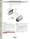


I
NVERTER BOARD
IGBT
C
hannel A
IGBT
channel B
Emitter
Gate
C
ollector
Channel A
Collector
Channel B
Emitter
Gate
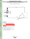
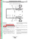
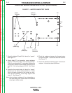
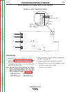
FIGURE F.6 – INVERTER BOARD TEST POINTS
INVERTER BOARD RESISTANCE TEST (CONTINUED)
PROCEDURE
1. Disconnect power to the INVERTEC® V155-S.
2. Perform the Case Cover Removal Procedure.
3. Perform the Input Filter Capacitor Discharge
Procedure
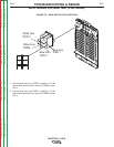
4. Visually check for burned areas on both sides of the
Inverter Board. If no obvious damage is evident,
continue to Step 5.
Note: The following tests may be performed without
dis-connecting the Board
5. Check the IGBTʼs for “shorts” using the
volt/ohmmeter in the diode test position, check each
IGBT from emitter to collector. See Figure F.6.
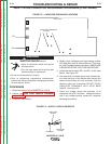
Note: Normal value is approximately 0.40 VDC in one
polarity and a charging value in the opposite
polarity.
The IGBTʼs of each channel are connected in par-
allel so it is only necessary to check one Emitter
to Collector of each channel.
6. Check each device from gate to emitter. See Figure
F.6
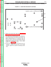
Note: Normal value is approximately .5VDC in both
polarities.
Note: Actual readings will vary depending on the meter
being used. Similar tests on all devices should
give similar results.
These devices will usually fail “shorted” resulting
in a zero or very low resistance reading from
Emitter to Collector. If they “open” physical dam-
age should be evident.
TROUBLESHOOTING & REPAIR
F-16 F-16
INVERTEC® V155-S
Return to Section TOC Return to Section TOC Return to Section TOC Return to Section TOC
Return to Master TOC Return to Master TOC Return to Master TOC Return to Master TOC