


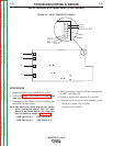
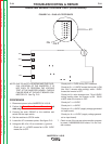
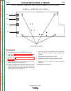


DC+
DC-
INPUT BOARD
AC2
AC
1
MOUNTING SCREWS
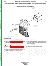
FIGURE F.11 – SCREW AND LEAD LOCATION
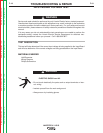
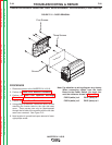
INPUT BOARD REMOVAL AND REPLACEMENT PROCEDURE
PROCEDURE
1. Disconnect power to the INVERTEC® V155-S.
2. Perform the Case Cover Removal Procedure
(Left side only).
3. Perform the Input Filter Capacitor Discharge
Procedure.
4. Label and disconnect the four leads at the Power
Switch located on the case back.
5. Using a 7mm nutdriver, remove the four input board
mounting screws. This will allow the board to be
gently pulled forward to gain access to associated
leads and plugs. See Figure F.11.
.
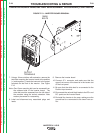
6. Label and remove all associated leads and plugs.
Some leads will require a 7mm nutdriver for
removal
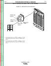
7. Remove and replace the Input board.
8. Connect all leads and plugs previosly removed
9. Replace the four mounting screws previously
removed.
10. Replace the case cover.
TROUBLESHOOTING & REPAIR
F-26 F-26
INVERTEC® V155-S
Return to Section TOC Return to Section TOC Return to Section TOC Return to Section TOC
Return to Master TOC Return to Master TOC Return to Master TOC Return to Master TOC