


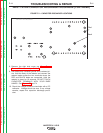
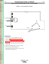


INVERTER BOARD
D9
Collector
Channel B
D7
D3
Output
Terminals
Point 2
Point 1
(center leg)
R24 = PTC
(solder pad)
Collector
Channel A
Red
Black
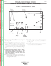
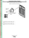
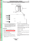
FIGURE F.7 – INVERTER BOARD TEST POINTS
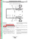
INVERTER BOARD RESISTANCE TEST (CONTINUED)
7. Check the diodes D3 and D9 for “shorts” or “opens”.
See Figure F.7.
8. Check diode D7, but remember, some resistance
(approx. 27-28 ohms) will be read in both polarities.
This will occur because D7 is a snubber diode and is
connected in parallel to the snubber resistors R8, R9
and R10. See wiring diagram X0519. See Figure
F.7.
9. Check the five output diodes for “shorts” or “opens”.
Check from the center terminal (Point 1) of each
Diode (all center terminals of the diodes are com-
mon with the heatsink) to the large copperl area
“point 2”. See Figure F.7.
Note: Actual voltage readings will vary depending on
the meter being used. Similar tests on all devices
should give similar results
10. Check the resistance between the thermal protec-
tion terminals R24. It should be about 36-40 ohms.
See Figure F.7.
11. Check the resistance between output terminal con-
nections. It should be about 8.5Kohms.
TROUBLESHOOTING & REPAIR
F-17 F-17
INVERTEC® V155-S
Return to Section TOC Return to Section TOC Return to Section TOC Return to Section TOC
Return to Master TOC Return to Master TOC Return to Master TOC Return to Master TOC