


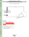
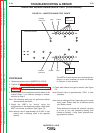
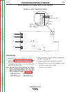

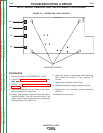

DC+
DC-
I
NPUT BOARD
AC2
AC1
JP1
PIN 2
PIN 1
PIN 3
PIN 4
PIN 8
PIN 12
PIN 14
FIGURE F.8 – INPUT BOARD TEST POINTS
INPUT BOARD VOLTAGE TEST (CONTINUED)
PROCEDURE
1. Disconnect power to the INVERTEC® V155-S.
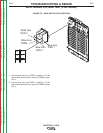
2. Perform the Case Cover Removal Procedure (left
side only).
3. Connect the main 230VAC to the the machine and
switch ON the input switch.
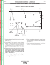
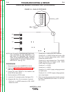
Note: Pay attention to wiring diagram very closely.
When connecting cables from the Input
Board to the Power Switch. You must con-
nect the cables as shown in Figure F.9.
PWR 2(white) to 4 PWR 1(blue) to 1
PWR 4(white) to 5 PWR 3(blue) to 2
4. Using a multimeter, check for 230VAC between AC1
and AC2. See Figure F.8.
5. Check for 320-325VDC between DC+ and DC-
6. Using pin 8,9,15 or 16 of JP1 as a common (-) point:
Check pin 2,4 and 14 for +15VDC.
Check pin 12 for +5VDC.
TROUBLESHOOTING & REPAIR
F-20 F-20
INVERTEC® V155-S
Return to Section TOC Return to Section TOC Return to Section TOC Return to Section TOC
Return to Master TOC Return to Master TOC Return to Master TOC Return to Master TOC