


21
Section 4 Maintenance and Lubrication
7/14/08
RCR2584 Rotary Cutter 312-459M
Land Pride
Table of Contents
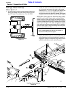
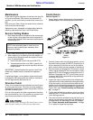
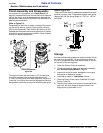
Clutch Assembly and Disassembly
If the clutch run-in procedure, see "Clutch Run-In"on
page 20, indicated that one or more of the friction disks did
not slip, the clutch must be disassembled to separate the
friction discs. Refer to the Parts Section of this manual for a
detailed parts breakdown.
Refer to Figure 5-2:
Disassembly of the clutch is simply a matter of first remov-
ing the spring retainer nuts (#1), springs (#2) and bolts
(#3) from the assembly. Each friction disc (#4) must then
be separated from the metal surface adjacent to it. Inspect
all parts for excessive wear and condition. Clean all parts
that do not require replacement.
The original friction disc thickness is 1/8" (3.2mm) and
should be replaced if the thickness falls below 3/64"
(1.1mm). If the clutches have been slipped to the point of
"smoking", the friction discs may be damaged and should
be replaced. Heat build-up may also affect the yoke joints.
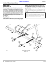
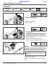
Refer to Figure 5-3:
Install new friction discs if needed and reassemble all com-
ponents in proper order. Progressively tighten each spring
retainer bolt until the spring length is 1.010” to 1.120” for
540 RPM.
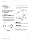
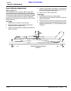
Storage
At the end of the working season or when the cutter will not
be used for a long period, it is good practice to clean off
any dirt or grease that may have accumulated on the cut-
ter and any of the moving parts.
1. Clean the Rotary Cutter as necessary.
2. Check the blades for wear and replace if necessary,
see "Service Cutting Blades", Page 20.
3. Inspect the cutter for loose, damaged or worn parts
and adjust or replace as needed.
4. Lubricate as noted in "Lubrication", below.
5. Store the Rotary Cutter inside if possible for longer
Rotary Cutter life.
6. Repaint parts where paint is worn or scratched to pre-
vent rust. Ask your dealer for Aerosol Land Pride
Beige touch-up paint #821-011C.
Clutch Disassembly
Figure 5-2
14714
Clutch Adjustment
Figure 5-3
20904