


10
Section 1 Assembly and Setup
RCR2584 Rotary Cutter 312-459M 7/14/08
Land Pride
Table of Contents
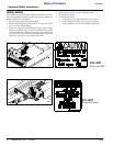
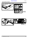
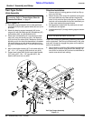
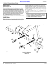
Trail-Type Tongue Assembly
Figure 1-5
14386
Trail-Type Cutter
Hitch Assembly
Refer to Figure 1-5:
1. Assemble tongue weldment (#1) to deck weldment
using two hitch pins (#2), spacer tubes (#3) and lynch
pins (#4).
2. Attach the bearing support assembly (#5) to the
tongue (#1) with two bushings (#6), flat washers (#7),
lock washers (#8), nut (#9) and bolt (#10).
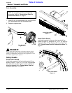
3. Attach level rod assembly (#11) to the tongue weld-
ment (#1) using two clevis pins (#12), flat washers
(#13) and hair pin cotters (#14). Make sure that the
adjusting nut on the level rod assemblies is threaded
the same distance on both level rod weldment long
and level rod weldment short. This will ensure a level
unit.
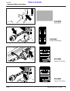
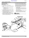
4. Mount hose holder bracket (#17) to the deck with the
3/4” -10 x 1 1/2” long bolt (#18) and lock nut (#19).
5. Fasten hose holder (#20) to the hose holder bracket
(#17) with a 3/8” -16 x 1 1/2” long bolt (#21), flat
washer (#22) and lock nut (#23).
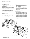
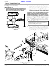
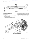
Driveline Installation
1. Remove wing nut holding gearbox shield and flip up
and out of the way.
2. Attach the slip clutch end of the jackshaft to the gear-
box input shaft securely. Make certain that the slip
clutch is fully onto the input shaft splines. Tighten the
two lock nuts on back side of slip clutch alternately un-
til they have reached the proper torque.
3. Swing gearbox shield back into place and re-install
the wing nut and tighten.
4. Insert jackshaft (#15) through bearing support assem-
bly (#5).
Install main driveline to jackshaft by attaching (red) slide
collar to jackshaft. Twist the quick disconnect on the yoke
and push it forward to engage the groove on the splined
stub on the jackshaft.
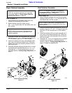
5. Secure chain on driveline (#16) to bearing support as-
sembly (#5) to restrict outer shield from rotating. Se-
cure chain on driveline (#15) to level rod weldment to
restrict outer shield from rotating.
NOTE: Do not tighten hardware until assembly
is complete. Refer to “Torque Values Chart for
Common Bolt Sizes” on page 27.
NOTE: Be sure lock collar is to the rear.