


20
Section 4 Maintenance and Lubrication
RCR2584 Rotary Cutter 312-459M 7/14/08
Land Pride
Table of Contents
Section 4 Maintenance and Lubrication
Maintenance
Proper servicing and adjustment is the key to the long life
of any farm implement. With careful and systematic in-
spection, you can avoid costly maintenance, time and re-
pair.
After using your Rotary Cutter for several hours, check all
bolts to be sure they are tight.
Replace any worn, damaged or illegible safety labels by
obtaining new labels from your Land Pride Dealer.
Service Cutting Blades
1. Both blades should be sharpened at the same angle
as the original cutting edge and must be replaced or
reground at the same time to maintain proper balance
in the cutting unit.
2. Both blades should weigh the same after sharpening.
3. When replacing or sharpening the cutter blades, ex-
amine bolts for excessive wear and replace if neces-
sary. To replace blades:
a. Order blade bolt Land Pride part # 802-277C.
b. Torque blade bolt lock nut to 450 ft. pounds. An
extended cheater bar may be required to achieve
proper torque.
IMPORTANT: Replace blades with genuine Land Pride
blades only. Blades must be ordered and replaced in
pairs.
If replacing dishpan, nut on gearbox output shaft should
be torqued to 450 foot/pounds and cotter pin installed in
nut with legs securely bent around nut.
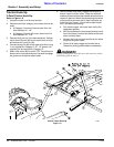
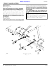
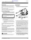
Driveline Clutch
Cutter drive components are protected from shock loads
by a four plate slip clutch. The clutch must be capable of
slippage during operation to protect the gearbox, driveline
and other drivetrain parts.
Prior to initial operation and after long periods of inactivity,
the clutch should be "run-in" to remove any oxidation that
may have accumulated on the friction surfaces.
!
CAUTION!
Engage parking brake, disengage PTO, shut off tractor, and re-
move key before making any of the following adjustments.
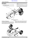
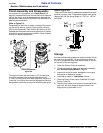
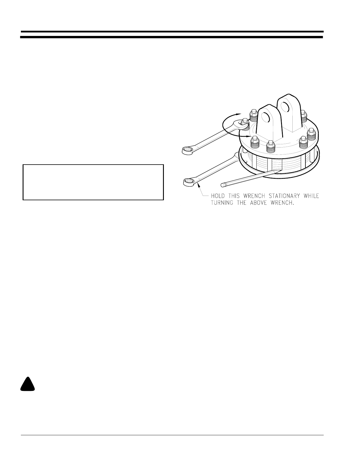
Clutch Run-In
Refer to Figure 5-1:
1. Using a pencil or other marker, scribe a line across the
exposed edges of the clutch plates and friction disks.
2. Carefully loosen each of the 8 spring retainer nuts on
the clutch housing a total of EXACTLY 2 revolutions. It
will be necessary to hold the hex end of the retainer
bolt in order to count the exact number of revolutions.
3. Start the tractor and engage the PTO drive for 2-3 sec-
onds to permit slippage of the clutch surfaces. Disen-
gage the PTO, then re-engage a second time for 2-3
seconds. Disengage the PTO, shut off tractor and re-
move key. Wait for all components to stop before dis-
mounting from tractor.
4. Inspect the clutch and ensure that the scribed mark-
ings made on the clutch plates have changed position.
If any two marks on a friction disk and plate are still
aligned, such indicates that slippage has not occurred
and the clutch must be disassembled to separate the
friction disks, see "Clutch Assembly and Disassem-
bly", on page 21.
5. Tighten each of the 8 spring retainer nuts on the clutch
housing EXACTLY 2 revolutions to restore the original
clutch setting pressure.
6. The clutch should be checked during the first hour of
cutting and periodically each week. An additional set
of scribe marks can be added to check for slippage.
See "Clutch Assembly and Disassembly", on page
21, to adjust for proper spring length.
NOTE: Care should be taken in order not to re-
move any more material than necessary when
sharpening blades.
Clutch
Figure 5-1
13693