


9
Section 1 Assembly and Setup
7/14/08
RCR2584 Rotary Cutter 312-459M
Land Pride
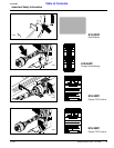
Table of Contents
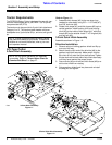
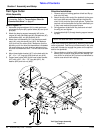
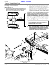
Single Tailwheel Assembly
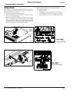
Refer to Figure 1-3:
1. Slide tailwheel arm adjustment plate (#10) onto
tailwheel arm weldment (#1) as shown.
2. Attach tailwheel tube (#1) to deck using a
5/8” -11 x 3” long bolt (#2), 5/8” lock washer (#3), and
5/8” nut (#4).
3. Assemble tailwheel mounting bracket (#5), and (#6) to
deck with four 1/2” -13 x 1 1/2” long carriage bolts (#7),
1/2” flat washers (#8), and 1/2” lock nuts (#9).
4. Install shim washer (#14) onto yoke assembly (#15)
then insert into tailwheel weldment (#1). Slide shim
washer (#14) onto yoke assembly shaft and secure
with roll pin (#16).
5. Assemble tailwheel adjusting bracket (#10), to mount-
ing brackets (#5), and (#6) with two 1/2” -13 x 1 1/2”
long bolts (#11), 1/2” lock washers (#12), and 1/2”
nuts (#13). Refer to “Cutting Height Adjustment” on
page 17.
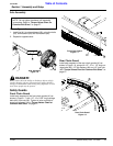
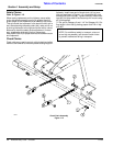
Dual Tailwheel Assembly
Refer to Figure 1-4:
1. Attach tailwheel weldment (#1) to tailwheel bracket
weldment (#2) with a 5/8” -11 x 3” long bolt (#3), 5/8”
lock washer (#4), and 5/8” nut (#5).
2. Assemble tailwheel adjusting bracket (#6), and (#7) to
the deck using four 1/2” -13 x 1 1/2” long carriage bolts
(#8), and 1/2” lock nuts (#9) and 1/2” flat washers
(#17).
3. Install shim washer (#10) onto yoke assembly (#11)
then insert into tailwheel weldment (#1). Slide shim
washer (#10) onto yoke assembly shaft and secure
with roll pin (#12).
4. Install two 1/2” -13 x 3 1/2” long bolts (#14), lock wash-
ers (#15), and nuts (#16), in adjusting mounts
(#6 & #7). Refer to “Cutting Height Adjustment” on
page 18. Repeat for opposite side.
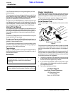
NOTE: Do not tighten hardware until assembly
is complete. Refer to “Torque Values Chart for
Common Bolt Sizes” on page 27.
NOTE: Install in hole shown if chainguards are
installed, otherwise move components to hole
closest to gearbox.
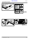
Single Tailwheel Assembly
Figure 1-3
14384
NOTE: Do not tighten hardware until assembly
is complete. Refer to “Torque Values Chart for
Common Bolt Sizes” on page 27.
NOTE: Install in hole shown if chainguards are in-
stalled, otherwise move components to hole clos-
est to gearbox.
Dual Tailwheel Assembly
Figure 1-4
14385