


8
Section 1 Assembly and Setup
RCR2584 Rotary Cutter 312-459M 7/14/08
Land Pride
Table of Contents
Section 1 Assembly and Setup
Tractor Requirements
The RCR2584 Rotary Cutter is designed for use with trac-
tors that are equipped with a (540 RPM 1 3/8”-6 spline)
rear power take-off (PTO).
The tractor must also provide for 3-point hitch attachment
Category II or III. The tractors rated drawbar minimum
horsepower on a 3 point to be 60 hp., and on a trail type 40
hp.
Lift-Type Cutter
3-Point Hitch Assembly
NOTE: In order to maintain steering control, ballast
may need to be added to your tractor. To determine
whether or not to add the ballast, refer to your trac-
tor’s operator manual.
NOTE: Do not tighten hardware until assembly
is complete. Refer to “Torque Values Chart for
Common Bolt Sizes” on page 27.
3-Point Hitch Assembly
Figure 1-1
14399
3-Point Quick Hitch Assembly
Figure 1-2
16440
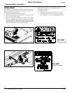
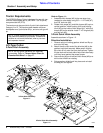
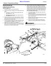
Refer to Figure 1-1:
1. Assemble hitch braces (#2) to the rear strap lugs
(welded to cutter deck) using 5/8" x 1 1/2" bolts (#7),
and 5/8" lock nuts (#8).
2. Rotate hitch straps (#1) and hitch braces (#2) up to a
vertical position. Install bushing (#10) and pivoting
hitch (#3) to the inside of hitch straps (#1), with hitch
braces (#2) on the outside. Install 1” x 6” long bolt (#4)
and lock nut (#5).
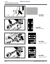
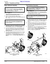
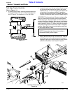
3-Point Quick Hitch Assembly
Assemble as shown in Figure 1-2.
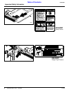
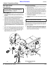
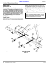
Driveline Installation
1. Remove wing nut holding gearbox shield and flip up
and out of the way.
2. Attach the slip clutch end of the driveline (#6) to the
gearbox input shaft securely. Make certain that the
slip clutch is fully onto the input shaft splines. Tighten
the two lock nuts on back side of slip clutch alternately
until they have reached the proper torque.
3. Secure chain (#9) on driveline to hitch brace (#2) to re-
strict outer shield from rotating.
4. Swing gearbox shield back into place and re-install
the wing nut and tighten.