


25
Section 5: Maintenance & Lubrication
2/02/08
RC5014 (540 RPM) and RCM5014 (1000 RPM) Rotary Cutters 330-117M
Land Pride
Table of Contents
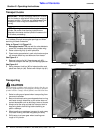
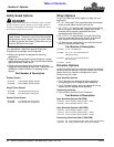
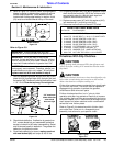
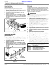
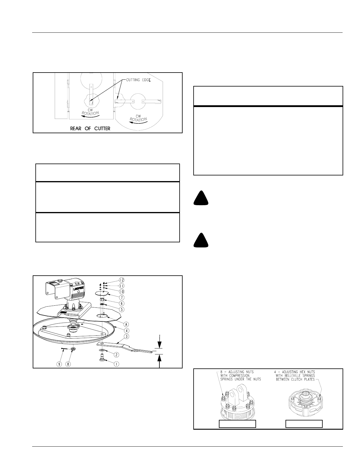
6. Refer to Figure 5-2: Carefully check cutting edges of
blades in relation to blade carrier rotation to ensure
correct blade placement. Cutter blades must be
installed with cutting edge leading in rotation. Airfoil
(lift) must be oriented towards the top of the deck.
Blade Rotation
Figure 5-2
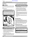
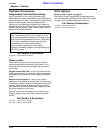
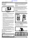
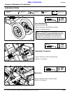
Refer to Figure 5-3:
7. Start by assembling blades without shim (#2). Insert
blade bolt (#1) through blade (#3), dish pan (#4) and
flat washer (#5). Temporarily secure blade with a used
1 1/8"-12 nut. Draw nut up snug. Do not tighten.
Cutter Blade Assembly
Figure 5-3
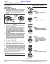
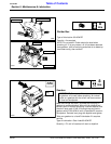
8. Check blade deflection. If deflection is greater than
3/4", remove blade bolt and reassemble as before
except include shim (#2) when reassembling. Select
shim thickness based on deflection. The greater the
deflection, the thicker the shim.
9. Once blade deflection is correct, replace used nut
with new locknut (#6) and torque to 450 ft. lbs.
IMPORTANT: Examine blade bolts (#1) and
washers (#5) for excessive wear and replace if worn.
IMPORTANT: Shim (#2) may or may not be
required. If blade deflection is less than 3/4" without
a shim, then the shim is not used. However, a shim
is required if blade deflection is greater than 3/4".
IMPORTANT: Locknuts can loose their ability to
lock properly once removed. Therefore, always use
a used blade nut or plain nut in steps 7 & 8 and then
replace used nut with new locknut in step 9.
3/4" maximum
blade deflection
when blade
bolts are tight
26675
10. If replacing dishpan (#4), nut (#8) on gearbox output
shaft should be torqued to 550 ft-lbs. minimum and
secured with cotter pin (#9) with both legs bent
opposite directions around the nut.
11. Replace access cover (#7) with flat washers (#10),
lock washers (#11) and wing nuts (#12).
12. Reconnect main driveline to tractor PTO shaft.
Drivelines With Slip Clutches
!
CAUTION
Engage parking brake, disengage PTO, shut off tractor, and
remove key before working on or around the driveline and/or
slip clutch.
!
CAUTION
Slip clutches that have been in use or have been slipped for only
two or three seconds during run-in may be too hot to touch.
Allow a hot clutch to cool before working on it.
Cutter drive components are protected from shock loads
by a friction slip clutch. The clutch must be capable of
slippage during operation to protect the gearbox,
driveline and other drive train parts.
Friction clutches should be “run-in” prior to initial
operation and after long periods of inactivity to remove
any oxidation that may have accumulated on the friction
surfaces. Repeat “run-in” instructions at the beginning of
each season and when moisture and/or condensation
seizes the inner friction plates.
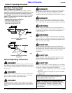
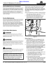
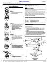
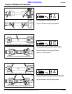
Refer to Figure 5-4 to determine which friction clutch
your cutter has. Follow run-In, disassembly and
assembly instructions for your specific clutch.
Clutch Types
Figure 5-4
Land Pride Cutter Blade Parts
Item Part No. Part Description
318-586A BLADE BOLT KIT (Item No’s 1, 2, 5 & 6)
)
1 802-277C BLADE BOLT 1 1/8-12 x 3 7/16 WITH KEY
2 312-075D BLADE SPACER 16 GA. (.06")
2 312-082D BLADE SPACER 18 GA. (.062")
2 312-089D BLADE SPACER 20 GA. (.036")
2 312-808D BLADE SPACER 24 GA. (.024")
3 820-249C CUTTER BLADE 1/2 x 4 x 23 CW
4 318-399D LARGE ROUND DISHPAN .19
5 804-147C WASHER FLAT 1 HARD ASTMF436
6 803-170C NUT HEX TOP LOCK 1 1/8-12 PLATE
Type A Clutch Type B Clutch
23560