


12
Section 1: Assembly and Set-up
RC5014 (540 RPM) and RCM5014 (1000 RPM) Rotary Cutters 330-117M 2/02/08
Land Pride
Table of Contents
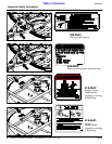
Hitch Types
The cutter is factory supplied with a standard clevis hitch.
The optional pintle hitch is also available. See your
nearest Land Pride dealer should you want to change
your hitch set-up.
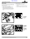
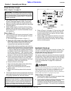
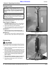
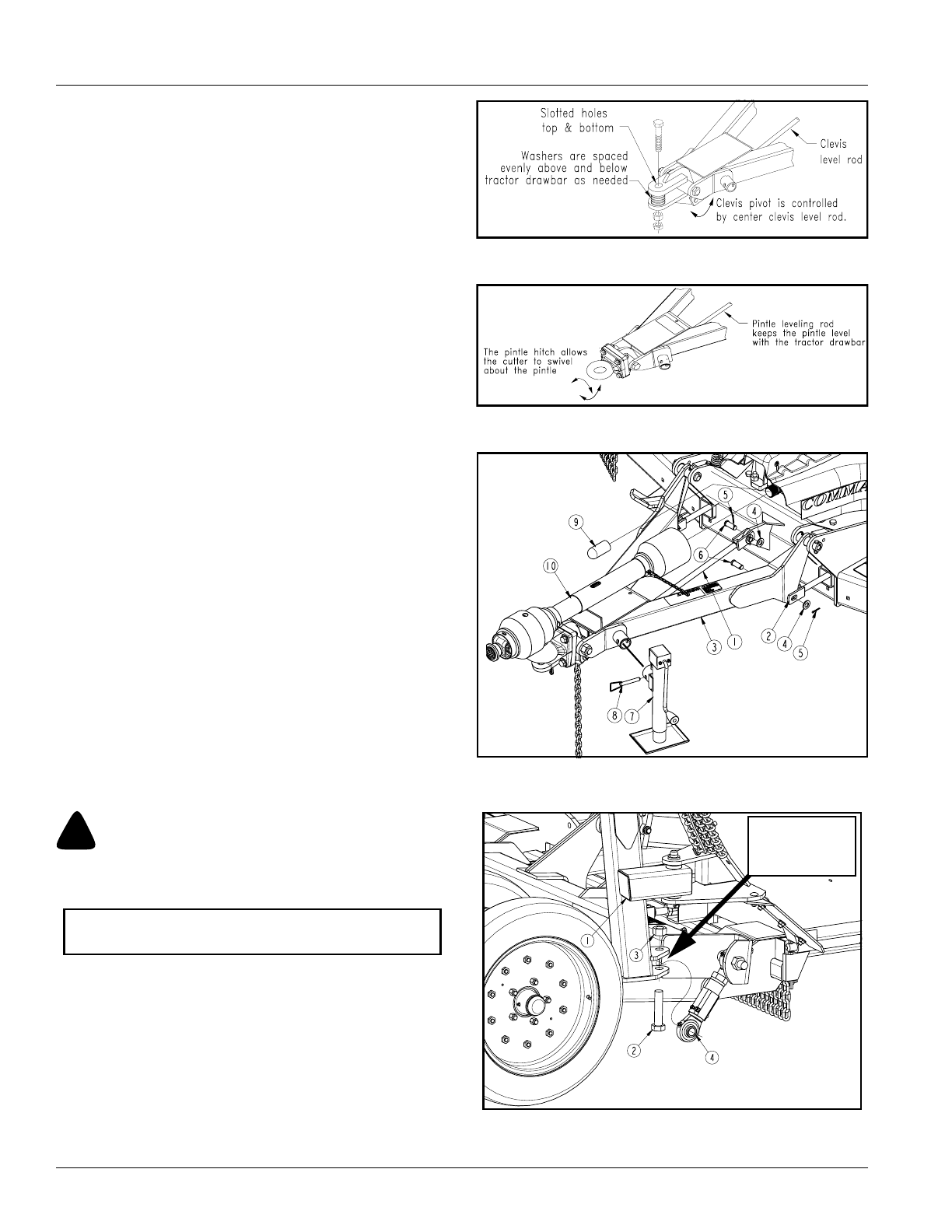
Standard Clevis Hitch
Refer to Figure 1-2:
A level rod attached to the underside of the clevis keeps
the clevis parallel with the tractor drawbar at all cutting
heights. Cutter rotation about the tractor drawbar is
limited to slots located in the clevis’ upper and lower
plates. Hitch should be secured to the tractor tongue with
bolt, washers and nuts to prevent spreading of clevis.
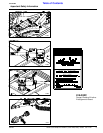
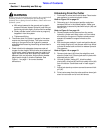
Pintle Hitch (Optional)
Refer to Figure 1-3:
A pintle leveling rod attached to the underside of the
pintle keeps the pintle parallel with the tractor drawbar at
all cutting heights. Cutter rotation about the tractor
drawbar is limited to movement about the pintle
connection.
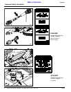
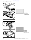
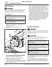
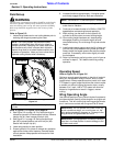
Hitch Assembly
Refer to Figure 1-4:
1. Install clevis rod (#1) to deck center lug using
3/4” x 1 1/2” clevis pin (#6), 3/4” flat washer (#4) and
5/32” x 1 1/4” cotter pin (#5).
2. Install left and right leveling rods (#2) to hitch
frame (#3) with 3/4” x 1 1/2” clevis pins (#6), 3/4” flat
washes (#4) and 5/32” x 1 1/4” cotter pins (#5). Final
adjustment should be made when the cutter is
attached to the tractor.
3. Install parking jack (#7) to hitch frame (#3) and
secure with attached pin (#8). Adjust parking jack to
preferred drawbar height.
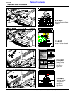
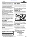
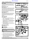
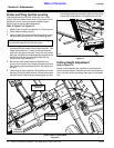
Wing Axle Assembly
Refer to Figure 1-5:
!
WARNING
Connect turnbuckle #4 between wing axle flanges before
lowering wing. Otherwise, personal injury and/or damage to
turnbuckle can occur.
Wing axles are secured folded backing for shipping
purposes.
1. Remove ties securing left and right wing axles (#1)
and rotate axles to install turnbuckles (#4).
2. Remove locknuts (#3) and cap screws (#2).
3. Attach left and right turnbuckles (#4) to wing axles
with existing 1”-8 Gr8 cap screws (#2) and 1” lock
nuts (#3). Make sure grease zerks are facing up
when wings are folded down.
4. Tighten locknuts (#3) to the correct torque.
NOTE: Do not tighten hardware until wing axle
assembly is complete.
Standard Clevis Hitch
Figure 1-2
Pintle Hitch
Figure 1-3
Hitch & Driveline Assembly
Figure 1-4
Wing Axle - Turnbuckle Assembly
Figure 1-5
22268
24730
24847
15336
Turnbuckle (#4)
to be secured
between the two
flanges.