


14
Section 1: Assembly and Set-up
RC5014 (540 RPM) and RCM5014 (1000 RPM) Rotary Cutters 330-117M 2/02/08
Land Pride
Table of Contents
Check Driveline Length
Refer to Figure 1-4 on page 12:
1. Park tractor and cutter in a straight line on a level
surface. Place gear selector in park, shut tractor
engine off, set park brake and remove switch key.
2. Remove protective shaft sleeve (#9) from input shaft
of splitter gearbox.
3. Attach bolted coupler of driveline (#10) to divider
gearbox shaft and pull-collar coupler to tractor PTO
shaft. Skip to step 5 if driveline fits between tractor
and implement.
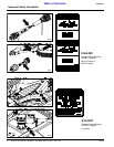
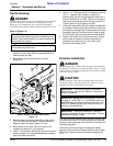
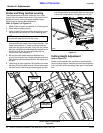
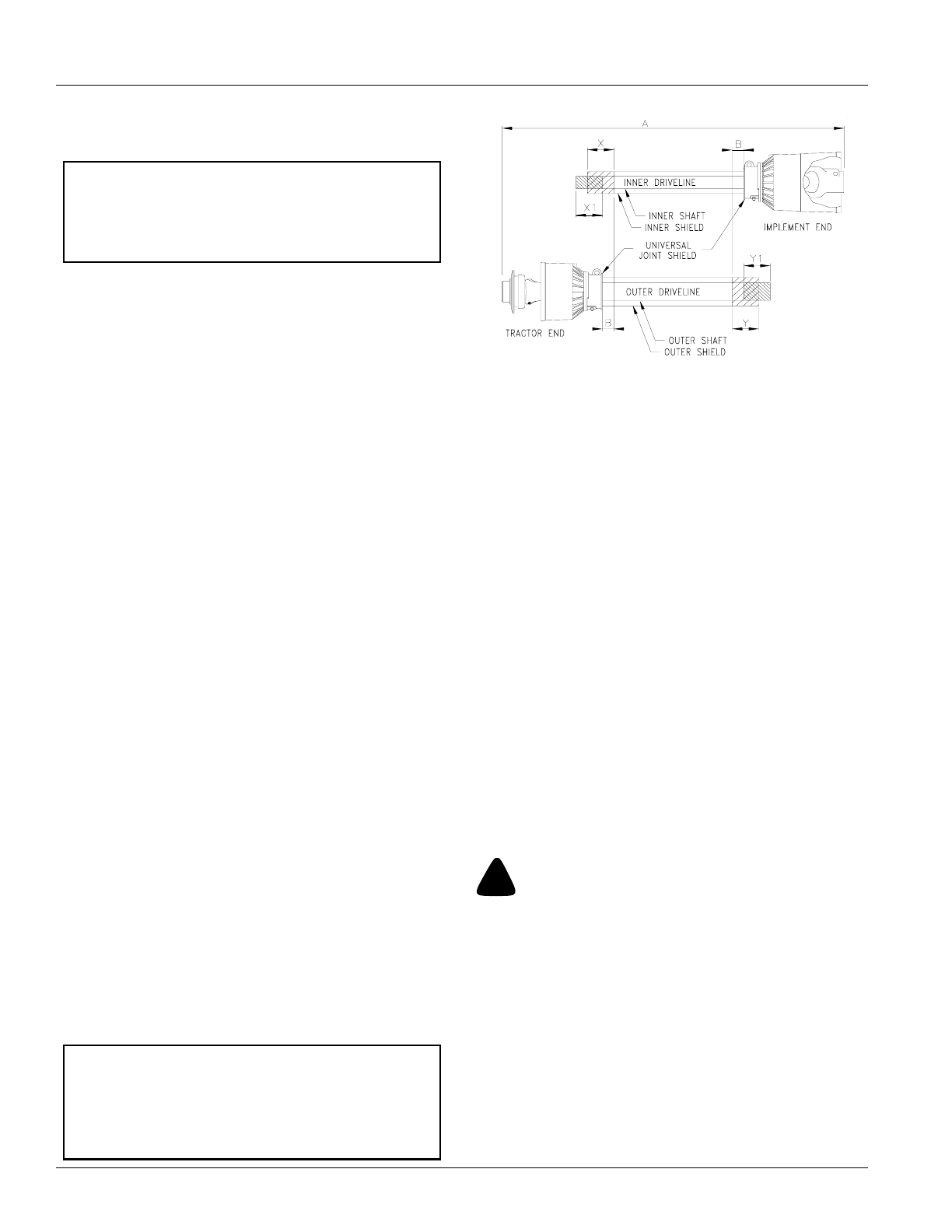
Refer to Figure 1-7:
4. The PTO driveline will require shortening if it does
not fit between tractor and cutter gearbox. Shorten
driveline as follows:
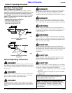
a. Pull driveline apart as shown in Figure 1-7.
b. Attach pull-collar coupler to the tractor PTO shaft
and bolted coupler to the divider gearbox shaft.
Pull on each driveline section to be sure the
universal joints are secured to the shafts.
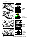
c. Hold driveline sections parallel to each other to
determine if they are too long. The inner and outer
shields on each section should end approximately
1" short of reaching the universal joint shield on
the adjacent section (see “B” dimension). If they
are too long, measure 1" (“B” dimension) back
from universal joint shield and make a mark at this
location on the inner and outer driveline shields.
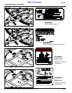
d. Cut off inner shield at the mark (“X” dimension).
Cut the same amount off the inner shaft (“X1”
dimension). Repeat cut off procedure (“Y”&“Y1”
dimensions) to the outer driveline half.
e. Remove all burrs and cuttings.
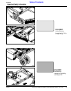
f. Apply multi-purpose grease to the inside of the
outer shaft and reassemble driveline.
g. Attach inner driveline yoke end to the divider
gearbox shaft.
h. Attach outer driveline yoke end to the tractor's
shaft.
5. The driveline should now be moved back and forth to
insure both ends are secured to the tractor and cutter
PTO shafts. Reattach any end that is loose.
IMPORTANT: The Rotary Cutter must be hitched to
the tractor with tractor and cutter aligned in a straight
line on a level surface. This arrangement will provide
the correct alignment between tractor PTO shaft and
gearbox input shaft.
IMPORTANT: Two or three small chains are
supplied with each driveline. These chains must be
attached to outer and inner driveline shields and to
cutter and tractor to restrict driveline shields from
rotating. If driveline has 3 chains, all 3 chains must
be secured to keep driveline shields from rotating.
PTO Driveline Shortening
Figure 1-7
6. Refer to Figure 1-6 on page 13. Secure chains (#6)
on driveline (#5) around hitch clevis rod to restrict
driveline outer shield from rotating. Re-latch safety
chain to driveline guard.
7. Attach safety chain located on the other end of the
driveline (#5) to the cutter’s main frame to restrict
driveline inner shield from rotating. Re-latch safety
chain to driveline guard.
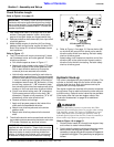
Hydraulic Hook-up
The cutter is equipped with two hydraulic cylinders. The
cylinder on the main deck lifts the cutter and the other
cylinder folds the wing. Both cylinders are set-up for
single action (one-way) operation.
Two duplex outlets are required at the tractor to operate
the cylinders. One to raise and lower the cutter and one
to fold the wing. Optional control valve kits are available
if the tractor does not have two duplex outlets. See
“Hydraulic Accessories” on page 23 for additional
information.
!
DANGER
Hydraulic fluid under pressure can penetrate skin. Wear
protective gloves and safety glasses or goggles when working
with hydraulic systems. Use a piece of cardboard or wood
rather than hands when searching for hydraulic leaks. If
hydraulic fluid is injected into the skin, it must be treated by a
doctor within a few hours or gangrene may result.
Refer to Figure 1-6 on page 13:
1. Route cylinder hoses (#7) through hose support loop
and connect to tractor remote outlets.
2. Cycle hydraulic system by raising and lowering center
deck cylinder and wing fold cylinder. It may be
necessary to purge the hydraulic system of trapped air
if operation is sluggish. The system may be purged as
follows:
22165