


15
Section 1: Assembly and Set-up
2/02/08
RC5014 (540 RPM) and RCM5014 (1000 RPM) Rotary Cutters 330-117M
Land Pride
Table of Contents
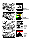
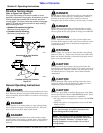
!
WARNING
Be sure center deck and wings are lowered to the ground and all
hydraulic pressure is relieved before disconnecting any
hydraulic lines or fittings between the Rotary Cutter and tractor
hydraulic system.
a. With wings lowered to the ground and hydraulic
pressure relieved, loosen hydraulic hose fitting at
each wing cylinder slightly to allow fluid to escape.
b. Slowly activate tractor control valve to purge any
trapped air from the system.
c. Tighten each fitting.
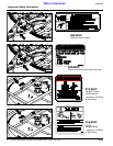
3. The center deck lift cylinder is purged in the same
manner as the wing cylinders. The cutter must be
resting on the ground and all hydraulic pressure
relieved before loosening hose fitting as described in
2a above.
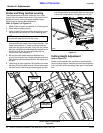
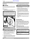
4. Check driveline for adequate clearance under all
ranges of cutter height. With driveline shaft attached
to the tractor, slowly raise and lower the cutter to its
upper and lower limits while observing clearances
between hitch and driveline. Adjust tractor drawbar
height and/or length if driveline interferes. See
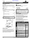
Figure 1-1 on page 11 for correct drawbar
dimensions.
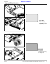
Unhooking From the Cutter
1. Park cutter on a level solid hard surface. Place tractor
gear selector in park and set park brake.
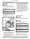
Refer to Figure 3-2 on page 18:
2. Raise wing up in the transport position and place
transport lock bar in the locked position. Make sure
transport bar is secured in place with lock pin (#2) and
hair pin (#1).
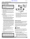
Refer to Figure 2-2 on page 16:
3. Remove stroke control spacers from the center
hydraulic cylinder and lower cutter until front skids
are resting on the ground. Replace stroke control
spacers as needed to support wheels at this
position.
4. With tractor gear selector in park and park brake set,
shut tractor engine off, and remove switch key. Move
cylinder lift levers back and forth to release hydraulic
line pressure.
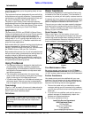
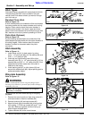
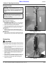
Refer to Figure 1-6 on page 13:
5. Remove jack stand (#3) from the weight box and
attach to cutter hitch. Secure jack stand in place with
attached jack pin (#8).
6. Unhook hydraulic hoses (#7), driveline safety
chains (#6), driveline (#5) and hitch safety chain (#4)
from the tractor. Store hose ends in hose support
loop.
7. Adjust jack stand up or down as need to remove hitch
pin (#1).
8. Drive tractor away from the cutter and then lower jack
stand to rest cutter on its front skid shoes.