


11
Section 1: Assembly and Set-up
2/02/08
RC5014 (540 RPM) and RCM5014 (1000 RPM) Rotary Cutters 330-117M
Land Pride
Table of Contents
Section 1: Assembly and Set-up
Tractor Requirements
Horsepower
Tractor horsepower should be within the range noted
below. Tractors outside the horsepower range must not
be used.
Horsepower Rating . . . . . . . . . . . . . . . . . .70-250 HP
Hitch
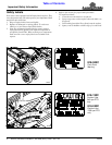
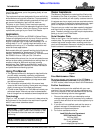
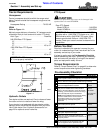
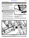
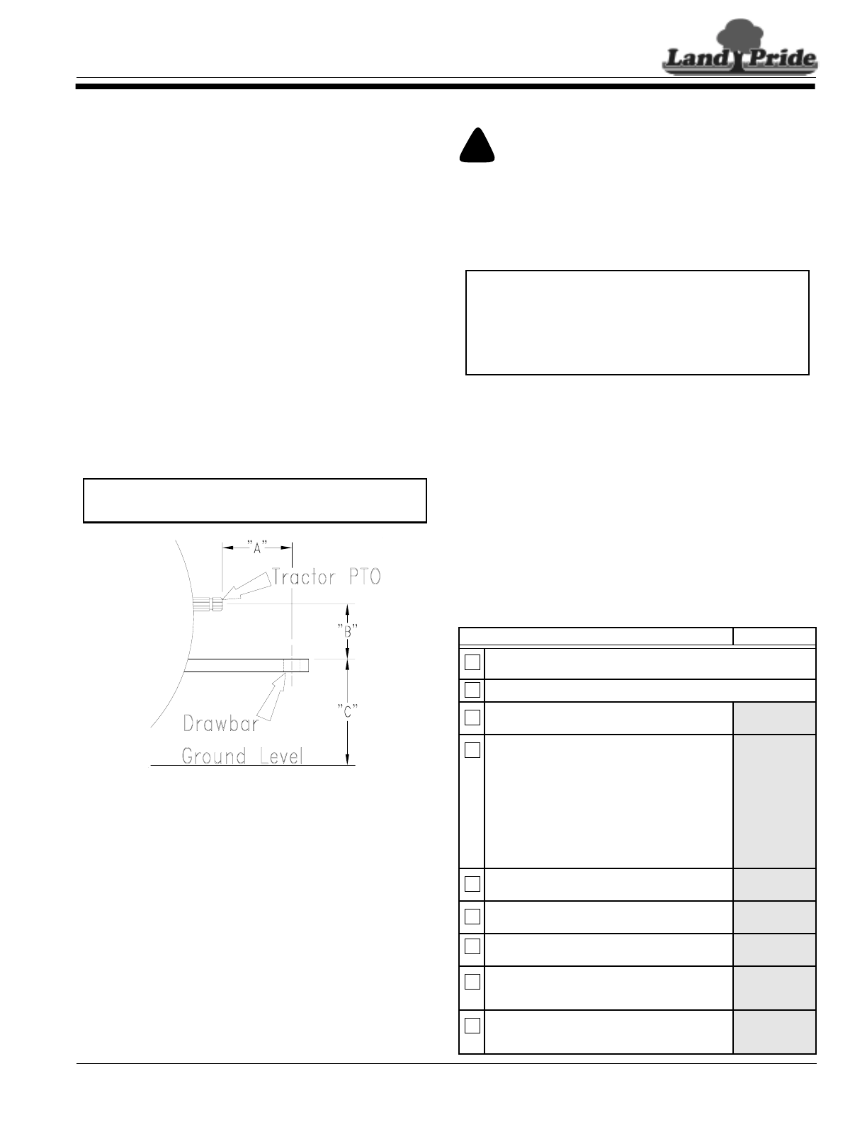
Refer to Figure 1-1:
Maintain proper distance, dimension “A”, between center
of drawbar hitch pin hole and end of tractor PTO shaft.
Hitch Type . . . . . . . . . . . . . . . . . . . . . . . . . . Draw Bar
540 RPM Rear PTO Speed:
“A”. . . . . . . . . . . . . . . . . . . . . . . . . . . . . . . . . . . 14"
“B”. . . . . . . . . . . . . . . . . . . . . . . . . . . . . . . . . . . . 8"
“C”. . . . . . . . . . . . . . . . . . . . . . . . . . . . . . 18" to 21"
1000 RPM Rear PTO Speed:
“A”. . . . . . . . . . . . . . . . . . . . . . . . . . . . . . . . . . . 16"
“B”. . . . . . . . . . . . . . . . . . . . . . . . . . . . . . . . . . . . 8"
“C”. . . . . . . . . . . . . . . . . . . . . . . . . . . . . . 18" to 21"
PTO to Drawbar Distance
Figure 1-1
Hydraulic Outlets
Two duplex outlets are required. One to raise and lower
the cutter and one to raise and lower the wing.
If your tractor is not equipped with two duplex outlets,
optional control valve kits are available from your local
Land Pride dealer. See “Hydraulic Accessories” on
page 23 for optional control valve kits.
IMPORTANT: PTO damage may occur if distance
“A” is not properly maintained.
22273
PTO Speed
!
CAUTION
Do not over speed PTO. The cutter can be damaged when
operated above its rated PTO RPM.
Rear PTO Speed:
Model RC5014 . . . . . . . . . . . . . . . . . . . . .540 RPM
Model RCM5014 . . . . . . . . . . . . . . . . . . .1000 RPM
Before You Start
Read and understand the operator’s manual for your
cutter. An understanding of how it works will aid in the
assembly and set-up of your cutter.
It is best to go through the Pre-Assembly Checklist
before assembling the cutter. Speed up your assembly
task and make the job safer by having all the needed
parts and equipment readily at hand.
Torque Requirements
Refer to “Torque Values Chart” on page 40 to determine
correct torque values when tightening hardware.
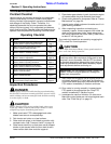
Pre-Assembly Checklist
Check Reference
Have a fork lift or loader with properly sized chains and safety
stands capable of lifting and supporting the equipment on hand.
Have a minimum of two people available during assembly.
Make sure all major components and loose
parts are shipped with the machine.
Operator’s
Manual
Double check to make sure all parts, fasteners
and pins are installed in the correct location.
Refer to the Parts Manual if unsure. By double
checking, you will lessen the chance of using a
bolt incorrectly that may be needed later.
NOTE: All assembled hardware from the factory
has been installed in the correct location.
Remember location of a part or fastener if
removed during assembly. Keep parts
separated.
Operator’s
Manual
330-323M
Parts Manual
330-323P
Make sure working parts move freely, bolts are
tight & cotter pins are spread.
Operator’s
Manual
Make sure all grease fittings are in place and
lubricated.
Page 30
Make sure all safety labels are correctly located
and legible. Replace if damaged.
Page 4
Make sure all red and amber reflectors are
correctly located and visible when machine is in
transport position.
Page 9
Make sure all tires are inflated to the specified
psi air pressure and all wheel bolts and axle
nuts are tightened to the specified torque.
Page 40
IMPORTANT: Do not attempt to operate a 540 RPM
driveline with a 1,000 RPM PTO tractor or a 1,000
RPM driveline with a 540 RPM PTO tractor. Many
tractors provide both 540 and 1,000 RPM PTO
modes. Check your tractor’s manual to determine its
capabilities.