


42
Section 5: Maintenance & Lubrication
ZT60i & ZT72i (S/N 748110+) Accu-Z
®
Zero Turn Mowers 357-552M
Table of Contents
2/06/14
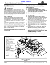
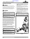
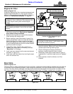
Evaporative Emission Control
System
Refer to Figure 5-11:
All Land Pride Zero Turn Mowers are EPA compliant as of
January 1, 2012 production date and include a decal
located on right side of engine stating the following: “This
Equipment meets U.S. EPA Evap. Standards”.
This Evaporative Emission Control System requires no
regularly scheduled maintenance but should be
inspected periodically, and thoroughly examined at least
once a year at the beginning of the mowing season:
1. Inspect all fuel system components including tanks,
vents, hoses, clamps, fuel filter, valves, and fittings
for leaks, cracks, and loose connections. Make
repairs as necessary.
2. The fuel tank is equipped with a tethered cap. Ensure
tether is present and secured to the cap.
3. The fuel cap has been designed to provide audible
and tactile feedback indicating that proper sealing
has been achieved. Ensure that this function is
present and that no fuel leaks from the filler neck
during usage. If fuel leakage is ever noticed at this
point, the fuel cap must be replaced immediately.
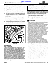
Fuel Filter
Refer to Figure 5-12 on page 43:
!
DANGER
Empty fuel tank before replacing fuel filter to keep fuel from
leaking out and creating a fire/explosion hazard.
The fuel filter is installed in the fuel line between the
fuel tank and engine fuel pump. Location of fuel filter will
vary depending on which engine your mower is equipped
with. See engine owner’s manuals for exact location of
fuel filter and instructions on removal and installation.
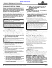
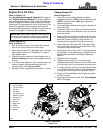
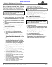
Refer to Figure 5-10:
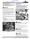
Replace fuel filter annually at the beginning of each
mowing season or after every 100 hours of operation,
whichever occurs first. (A plugged filter is considered a
maintenance item.) This will keep the fuel filter from
becoming plugged causing poor engine performance
and unexpected downtime. Be sure to install filter with
Flow Arrow pointing towards engine side of fuel line.
Fuel Filter
Figure 5-10
23803
(Flow Arrow) Indicates direction
fuel must flow through the filter.
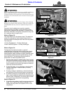
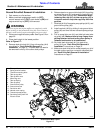
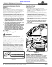
Drain Fuel Tank
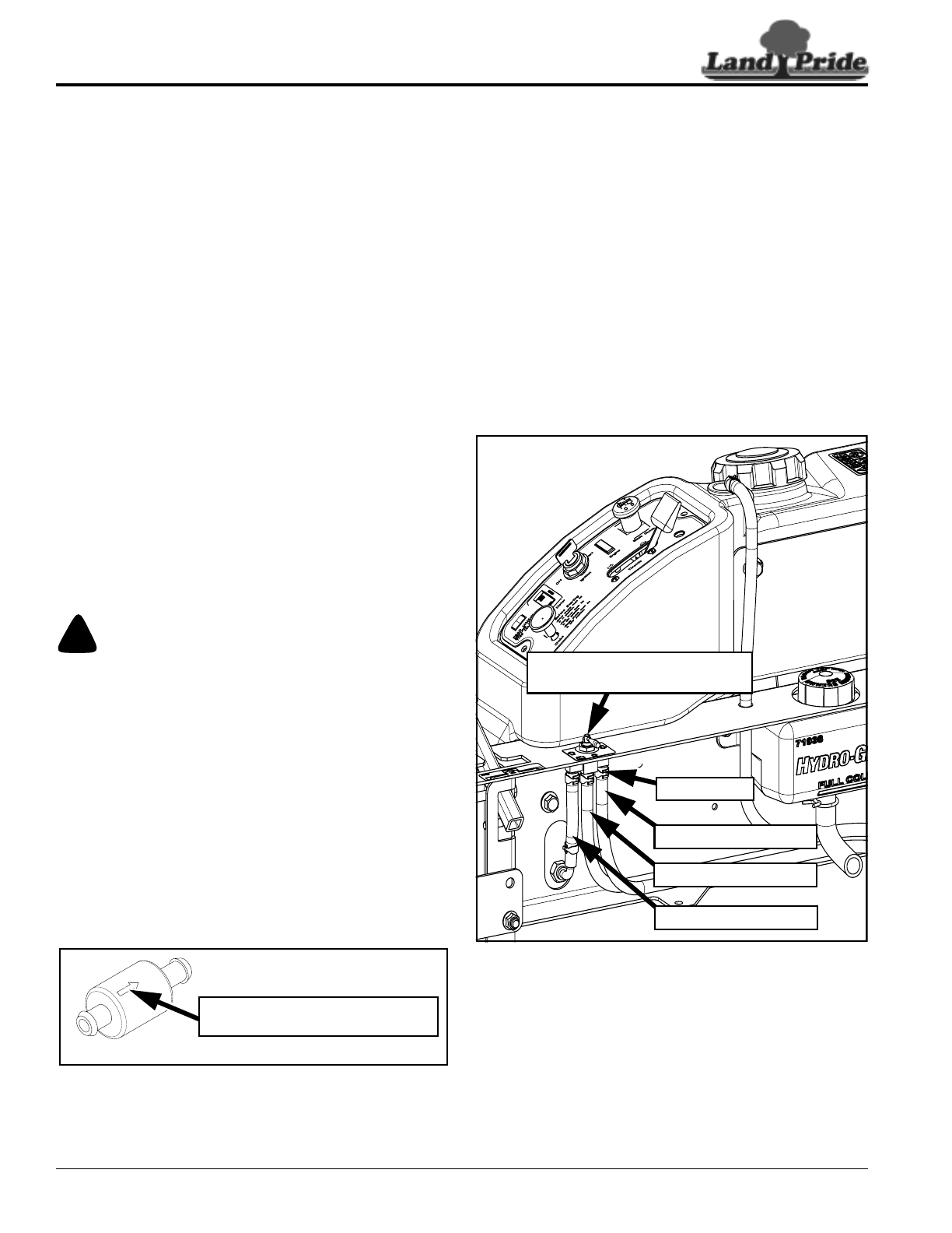
Refer to Figure 5-11:
1. Park unit on a flat surface. Make sure blade
engagement switch is (OFF), both control levers are
(OUT) and park brake is (ON). Stop engine and
remove ignition key.
2. Disconnect negative battery cable from the battery.
3. Trace fuel line from tank to be drained to the
Left/Right Fuel Tank Valve located on right side of
seat. Remove fuel line hose clamp at the Left/Right
Fuel Tank Valve and remove fuel line.
4. Place end of fuel line into a gas can or a drain pan to
drain fuel tank.
5. When fuel tank is drained, reattach fuel line to the
left/right fuel tank valve with previously removed
hose clamp.
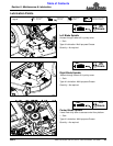
Fuel Lines (Raise Seat Platform to Access)
Figure 5-11
General Engine Maintenance
Detailed instructions and recommendations for break-in
and general maintenance are specified in the Engine
Operator’s Manual. Please refer to this manual for engine
servicing, lubricating oil levels with capacity and viscosity
recommendations, bolt torques, etc. The engine
warranty is backed by the engine manufacturer.
Special attention should be paid to applicable data which
is not duplicated here.
33812
Left/Right Fuel Tank Valve Center
Position “O” as Shown is OFF
Right Tank Fuel Line
Left Tank Fuel Line
Hose Clamps
Engine Fuel Line