


36
Section 5: Maintenance & Lubrication
ZT60i & ZT72i (S/N 748110+) Accu-Z
®
Zero Turn Mowers 357-552M
Table of Contents
2/06/14
!
WARNING
Do not overfill battery. Electrolytes may overflow and damage
paint, wiring and structure. Use soap and water when
cleaning the battery. Be careful not to get soap and water into
the battery. Use soda mixed in water to clean corrosion off the
terminals.
!
WARNING
Do not allow an open flame near the battery when charging.
Hydrogen gas forms inside the battery. This gas is both toxic
and flammable and may cause an explosion if exposed to a
flame.
Common circuit problems are usually caused by
electrical shorts, corroded, or dirty terminals, loose
connections, defective wire insulation, or broken wires.
Switches, solenoids, and ignition components may also
fail, causing a short or open circuit.
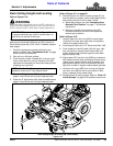
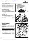
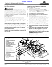
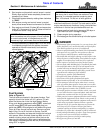
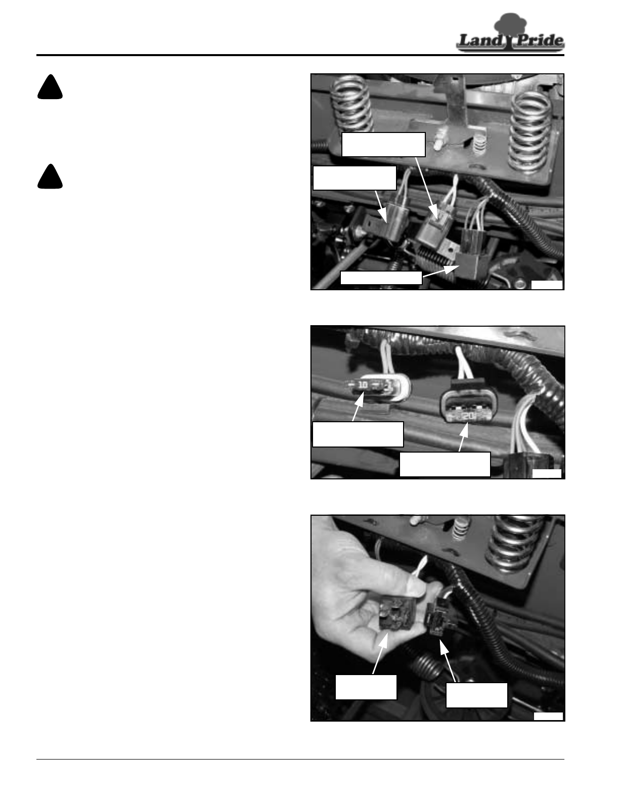
Refer to Figure 5-3:
The relay switch is for the starter circuit. The electrical
system is protected by fuses located along the wire
harness beneath the seat pan latch near the relay switch.
The fuses are:
• Clutch Engagement - 10 Amp, blade type
• Main Electrical System - 20 Amp, blade type
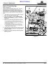
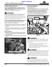
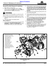
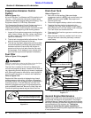
Refer to Figure 5-4:
To diagnose the electrical system, a general
understanding of electrical servicing and use of basic
test equipment is necessary for troubleshooting and
making repairs. Major overhaul or repair of starter motor
and charging system should be performed by trained
technicians only. The following checks should be
preformed if an electrical problem exist.
1. Remove fuse covers to access fuses. Visual inspect
each fuse for a broken circuit. A test light can be used
to check current across fuse terminals or remove the
fuse in question and use an ohm meter to check for
continuity across its terminals.
2. If fuses are good, use a voltmeter to check battery
voltage. Recharge or replace battery if battery
voltage is low.
3. If battery voltage is satisfactory, check cleanliness
and tightness of terminals and ground connections.
4. If terminals and ground connections are clean and
tight, visually inspect for defective wire insulation and
broken wires. If necessary, use a test light to check
for current to the component not operating.
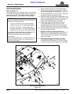
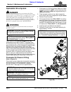
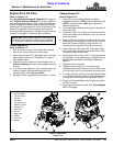
Refer to Figure 5-5:
5. If the electrical problem is with the starter motor and
steps 1 thru 4 above have been completed, then
unplug the relay switch and replace it with a new
relay switch.
Wiring Harness Fuses
Figure 5-3
Fuses Shown With Cover Removed
Figure 5-4
Relay Switch Shown Unplugged
Figure 5-5
33902
Relay Switch
10 Amp Fuse
Purple Wire Leads
20 Amp Fuse
White Wire Leads
33903
Uncovered Red
10 Amp Fuse
Uncovered Amber
20 Amp Fuse
33904
Unplugged
Relay Switch
Relay Switch
Receptacle