


16
Section 2: Operating Procedures
ZT60i & ZT72i (S/N 748110+) Accu-Z
®
Zero Turn Mowers 357-552M
Table of Contents
2/06/14
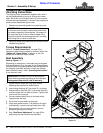
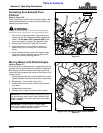
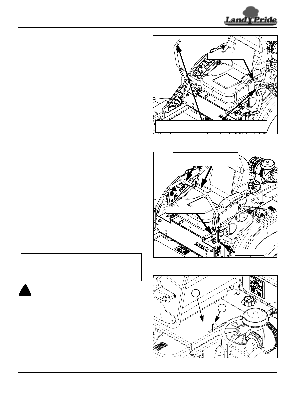
Park Brake
Refer to Figure 2-3 & Figure 2-4:
The park brake lever is linked to the wheel motors. The
rear wheels are kept from turning when park brake lever
is pulled back or to the (ON) position. Push lever forward
to (OFF) position to release park brakes.
Mower engine will stop running if park brake lever is set
to (ON) before spreading both control levers (OUT) or if
one or both control levers are moved (IN) before moving
park brake lever to (OFF).
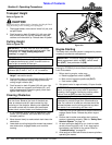
Control Levers
Refer to Figure 2-3 & Figure 2-4:
The control levers are used to steer, accelerate,
decelerate, stop, and change direction of travel.
Always move both control levers to neutral position and
then spread them fully (OUT) before setting park brake
lever to the (ON) position. Set park break to the (ON)
position. Always leave park brake and control levers in
this position until ready to start traveling. Move park
brake to (OFF) before pulling control levers (IN). Start
moving by moving control levers either forward or
rearward from neutral position.
See “Driving the Mower” on page 19 for a detailed
description of operating the control levers.
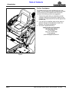
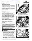
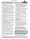
Accessing Area Beneath Seat
Platform
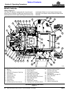
Refer to Figure 2-5:
The compartment below the seat platform (#2) is where
the control lever linkages, hydrostatic drives, belts, and
fuses are located. The seat is secured over this
compartment with a spring loaded seat latch (#1).
!
WARNING
The seat pan should always be latched in the down position
before starting mower. Not doing so can cause bodily injury.
1. Park unit on a flat level surface. Stop engine and
remove ignition key. Make sure blade engagement
switch is in the down (OFF) position. Spread
control levers fully apart and set park brake.
2. Pull latch arm (#1) to the left & lift seat platform (#2)
up to raise seat for viewing compartment below.
3. Close seat platform by lowering platform down until
latch arm catches on the seat platform. See “Seat
Reach Adjustment” on page 25 for positioning seat
forward and rearward.
NOTE: A carriage bolt may be inserted through
square hole in latch (#1) and secured with a nut.
Torque nut tight to prevent people from easily lifting
the seat platform while mower is operating.
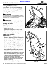
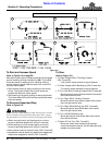
Control Levers Fully OUT (in Park Position)
Figure 2-3
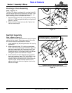
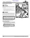
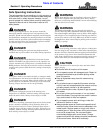
Control Levers Fully IN (In Neutral Position)
Figure 2-4
Seat Release Latch
Figure 2-5
33758
Park Brake (ON)
Both Control Levers Must Be Spread Fully (OUT)
Before Park Brake Is Engaged (ON).
33769
Control Levers (IN)
Neutral Operating Position
Neutral Slot
Park Brake (OFF)
33770
1
2