


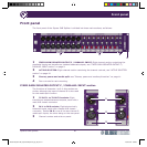

Rear panel
Square ONE Splitter 13
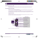
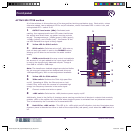
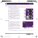
Media split and ground lift switches
The output lift and media split switches are deliberately recessed to prevent them being inadvertently
switched on or off. Each switch has an LED above for on/off indication, where illuminated LED = switch is
on, and extinguished LED = switch is off.
1 Red LED for OUTPUT A LIFT switch.
2 OUTPUT A LIFT switch: Recessed switch for
globally disconnecting the internal ground from the
OUT A output connector on all eight channels.
3 Red LED for OUTPUT B LIFT switch.
4 OUTPUT B LIFT switch: Recessed switch for
globally disconnecting the internal ground from the
OUT B output connector on all eight channels.
5 Yellow LED for MEDIA SPLIT switch. This
LED is duplicated on the front panel; see “ACTIVE
SPLITTER section” on page 10.
6 MEDIA SPLIT switch: Recessed switch for
switching the unit to media split mode; see “Media
split mode” on page 15 for details of operation.
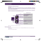
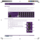
Mains supply
1 IEC socket: Auto voltage sensing, switch mode
power supply that operates where the nominal mains
voltage is in the range 100V a.c. to 240V a.c.
2 Fuse drawer: Contains the mains fuse at the
rear of a two-compartment drawer. The front
compartment contains a spare fuse. Always replace
the mains fuse (and spare) with the same type and
rating; see “Checking/replacing the mains fuse” on
page 28 for details.
3 Supply voltage and fuse specifications:
Details of the supply voltage and the mains fuse are
printed here.
4 Fuse warning information: Details on replacing the mains fuse with the same type is printed here.
1
2
3
4
5
6
21 43
DOC02-SQ1SPLITTER_Square ONE Splitter_Op_IssC.pdf 25 27/04/2010 17:00:43