


Rear panel
12 Square ONE Splitter
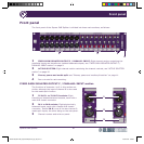
Rear panel
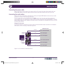
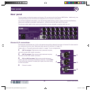
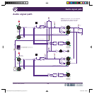
The rear panel provides the power and primary I/O connections for the Square ONE Splitter. Additionally, the
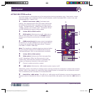
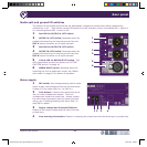
media split and ground lift switches are adjacent to the channel 8 connectors.
You will find important information, such as warnings and cautions, power supply and fuse specifications,
safety and compliance standards markings etc., printed on the left-hand side of the panel.
The correct mains lead for the country to which the unit was shipped is supplied with the unit.
Channel I/O connections
The functions of channels are 1 to 8 in this section are similar, although the input of channel 8 is also used for
the media split function (see “Media split and ground lift switches” on page 13).
Please refer to “Connecting the audio cables” on page 7 for pin assignments.
1 OUT A sockets: Eight electronically balanced outputs,
each with a male XLR chassis connector.
2 OUT B sockets: Eight electronically balanced outputs,
each with a male XLR chassis connector.
3 IN 1 to IN 8 sockets: Eight electronically balanced
inputs, each with a female XLR chassis connector. Socket IN 8
is one of the two channel 8 media split inputs, the other being
on the front panel.
4 Channel number.
1
2
3
4
4
DOC02-SQ1SPLITTER_Square ONE Splitter_Op_IssC.pdf 24 27/04/2010 17:00:43