


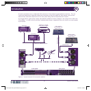
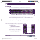

Front panel
10 Square ONE Splitter
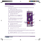
ACTIVE SPLITTER section
All of the switches in this section are of the two-position latching pushbutton type. Each switch, unless
otherwise stated, has an adjacent LED for on/off indication, where illuminated LED = switch is on, and
extinguished LED = switch is off.
1 OUTPUT level meter (dBu): Dedicated peak
reading, four-segment audio level LED meter that follows
the output level at all times, no matter how the controls
are set. The segments are: -15dBu (green); 0dBu (green);
+12dBu (yellow); and +21dBu (red). Illumination of the
red LED indicates the signal is being clipped.
2 Yellow LED for SOLO switch.
3 SOLO switch: Switches solo on/off. With solo on,
post mic amp gain audio is sent to the PHONES output,
allowing you to listen to and monitor the audio content
locally.
4 GAIN control knob: Nine-way control knob adjusts
the amount of mic gain added to the input signal before it
is sent to the electronically balanced outputs. Range is
from 0dB to +40dB in 5dB steps.
Note: The transformer isolated outputs are derived before
the mic amp gain stage and are buffered and driven at
-6dB operating gain, with no user adjustment available.
5 Yellow LED for 30Hz switch.
6 30Hz switch: Switches the 30Hz high pass filter
on/off. Operating at 30Hz, the filter acts as an ‘anti-
rumble’ filter, which aids the removal of unwanted high
energy low frequency elements in the audio signal.
7 Channel number and write-on panel.
8 +48V switch: Switches the +48V phantom power supply on/off.
Additionally, there is the facility of phantom power sensing provided on all electronic outputs that remotely
enables +48V on the splitter mic input XLRs when phantom power is activated from any attached console.
This is indicated by the illumination of its associated LED.
9 Red LED for +48V switch. This LED is for +48V switch on/off indication, but also illuminates when
phantom power is detected on either or both of the output XLRs (rear panel), even when the +48V switch is
off.
2
1
3
5
6
9
8
4
7
DOC02-SQ1SPLITTER_Square ONE Splitter_Op_IssC.pdf 22 27/04/2010 17:00:43