


SECTION 4.4
DIAGNOSTIC TESTS
PART 4
DC CONTROL
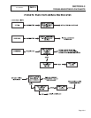
PROCEDURE:
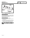
Disconnect all wires from switch terminals, to prevent
interaction. Then, use a volt-ohm-milliammeter (VOM)
to test for continuity across switch terminals as shown
in the following chart. Reconnect all wires and verify
correct positions when finished.
RESULTS:
1. Replace AUTO-OFF-MANUAL switch, if defective.
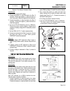
2. For Problem 8 Only: If the switch passes the tests,
verify the REMOTE NOT AUTO dipswitch is set to OFF
on the circuit board (see Figure 3, page 4.1-2) then
proceed to Test 44.
3. For Problem 9 Only: If the switch passes the tests,
proceed to Test 60.
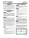
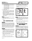
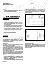
Figure 2. AUTO-OFF-MANUAL Switch Test Points
TTEESSTT
4444-
CCHHEECCKK
WWIIRREE
1155//1155AA//1177//223399
VVOOLLTTAAGGEE
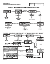
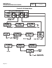
DISCUSSION:
The circuit board will not turn on unless battery
voltage is available to the board via wire 15, the
AUTO-OFF-MANUAL switch and Wire 15A. If battery
voltage is not available, automatic or manual
operation will not be possible.
Battery voltage is available to wire 17 from pin location
11 of the J1 connector on the circuit board. When the
AUTO-OFF-MANUAL switch is in the MANUAL position,
wire 239 supplies battery voltage to pin location 9 of the
circuit board, and engine cranking occurs.
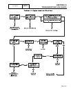
PROCEDURE:
(For Problem 1 flow chart, do Steps 1-5 and Step 9 only)
(For Problem 2 flow chart, do all steps)
1. Set a VOM to measure DC voltage.
2. Connect the positive (+) test lead to the AUTO-OFF-
MANUAL switch Terminal 2, Wire 15. Connect the
negative (-) test lead to a clean frame ground. Battery
voltage should be measured (See Figure. 2).
3. Connect the positive (+) test lead to the AUTO-OFF-
MANUAL switch terminal 1, Wire 15A. Connect the
negative (-) test lead to a clean frame ground. Set the
AUTO-OFF-MANUAL switch to MANUAL. Battery
voltage should be measured.
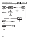
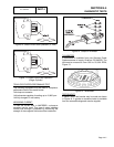
4. Connect the positive (+) test lead to Pin location 12 Wire
15 at the J1 connector on the circuit board. Connect the
negative (-) test lead to a clean frame ground. Battery
voltage should be measured.
5. Connect the positive (+) test lead to pin location 10, wire
15A at the J1 connector on the circuit board. Connect
the negative test lead to a clean frame ground. Set the
AUTO-OFF-MANUAL switch to the MANUAL position.
Battery voltage should be measured. Repeat Step 5.
This time set the AUTO-OFF-MANUAL switch to AUTO.
Battery voltage should be measured.
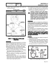
6. Connect the positive (+) test lead to pin location 9, wire
239 at the J1 connector on the circuit board. Connect the
negative (-) test lead to a clean frame ground. Set the
AUTO-OFF-MANUAL switch to the MANUAL position.
Battery voltage should be measured. If battery voltage
is measured, stop and proceed to results. If battery
voltage is NOT measured, proceed to Step 7.
Page 4.4-2
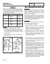
TERMINALS SWITCH POSITION READING
2 and 3 AUTO CONTINUITY
MANUAL INFINITY
OFF INFINITY
2 and 1 AUTO INFINITY
MANUAL CONTINUITY
OFF INFINITY
5 and 6 AUTO CONTINUITY
MANUAL INFINITY
OFF INFINITY
5 and 4 AUTO INFINITY
MANUAL CONTINUITY
OFF INFINITY