


SECTION 2.1
DESCRIPTION & COMPONENTS
PART 2
AC GENERATORS
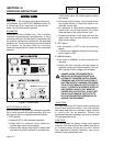
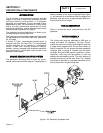
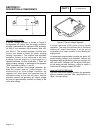
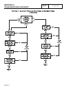
Figure 5. Excitation Circuit Breaker
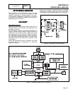
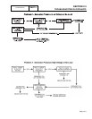
VOLTAGE REGULATOR:
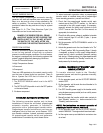
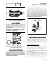
A typical voltage regulator is shown in Figure 6.
Unregulated AC output from the stator excitation
winding is delivered to the regulator’s DPE terminals,
via Wire 2, the excitation circuit breaker, Wire 162,
and Wire 6. The voltage regulator rectifies that
current and, based on stator AC power winding
sensing, regulates it. The rectified and regulated
excitation current is then delivered to the rotor
windings from the positive (+) and negative (-)
regulator terminals, via Wire 4 and Wire 1. Stator AC
power winding sensing is delivered to the regulator
"SEN" terminals via Wires 11 and 22.
The regulator provides "over-voltage" protection, but
does not protect against "under-voltage". On
occurrence of an "over-voltage’ condition, the
regulator will "shut down" and complete loss Of
excitation current to the rotor will occur. Without
excitation current, the generator AC output voltage
will drop to approximately one-half (or lower) of the
unit’s rated voltage.
Figure 6. Typical Voltage Regulator
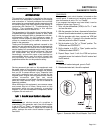
A single red lamp (LED) glows during normal
operation. The lamp will become dim if excitation
winding AC output diminishes. It will go out on
occurrence of an open condition in the sensing AC
output circuit.
An adjustment potentiometer permits the stator AC
power winding voltage to be adjusted. Perform this
adjustment with the generator running at no-load, and
with a 62 Hz AC frequency (62 Hz equals 3720 rpm).
At the stated no-load frequency, adjust to obtain a
line-to-line AC voltage of about 252 volts.
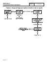
MAIN LINE CIRCUIT BREAKER:
The main line circuit breaker protects the generator
against electrical overload. See Specifications on
Page 1 for amp ratings.
Page 2.1-3