


SECTION 4.4
DIAGNOSTIC TESTS
PART 4
TEST
52
-
TEST
FUEL
SOLENOID
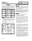
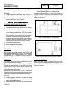
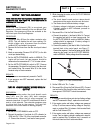
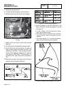
Note:
This
test
is
for
fuel
regulators
equipped
with
idle
circuit
port
only.
See
Figure
16.
These
units
have
an
additional
1/4”
fuel
hose.
DISCUSSION:
When the Fuel Solenoid (FS) is energized, gas
pressure is available internally to the on demand Fuel
Regulator. Gas pressure will then be available to the
idle circuit port of the Fuel Regulator.
PROCEDURE:
1. Disconnect Wire 56 from the starter contactor relay
(SCR). This will disable the unit from cranking. For
single cylinder units, disconnect from the starter
contactor (SC) and isolate it from ground.
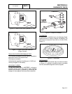
2. Remove the fuel hose from the idle circuit port barbed
fitting.
3. Attach a manometer (Generac P/N 0C7977) to the idle
circuit port barbed fitting.
4. Set the AUTO-OFF-MANUAL switch to MANUAL. The
engine will not crank, but gas pressure should be
observed on the manometer at 11”-14” of water column.
5. Set the AUTO-OFF-MANUAL switch to OFF. Remove
the manometer. Re-attach the fuel hose to the idle circuit
port barbed fitting. Re-connect Wire 56 to the starter
contactor relay or starter contactor.
RESULTS:
1. If gas pressure was measured, proceed to Test 55.
2. If gas pressure was NOT measured, replace the fuel
solenoid (FS).
TEST
53
-
CHECK
CIRCUIT
BOARD
WIRE
14
OUTPUT
DISCUSSION:
During any cranking action, the circuit board’s crank
relay (K1) and run relay (K2) both energize
simultaneously. When the run relay energizes, its
contacts close and 12 volts DC is delivered to Wire 14
and to a fuel solenoid. The solenoid energizes open
to allow fuel flow to the engine. This test will
determine if the circuit board is working properly.
PROCEDURE:
1. Set the AUTO-OFF-MANUAL switch to OFF.
2. Connect the positive (+) test lead of a DC voltmeter (or
VOM) into Pin 7 (Wire 14) of the circuit board connector
J1. Connect the common (-) test lead to frame ground.
3. While observing the meter, set the AUTO-OFF-MANUAL
switch to MANUAL.
a.The circuit board’s crank and run relays should
energize and the engine should crank and start.
b.The meter should indicate battery voltage.
c. If battery voltage is indicated, proceed to Step 4.
If battery voltage is NOT indicated, proceed to
Test 53 results.
4. Disconnect Wire 14 at the Fuel Solenoid (FS).
a.Connect the positive (+) test lead to Wire 14. Connect
the negative test lead to a clean frame ground. Set
the AUTO-OFF-MANUAL switch to MANUAL. Battery
voltage should be measured. If battery voltage is
indicated, proceed to Step 5.
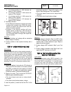
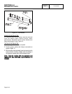
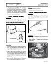
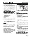
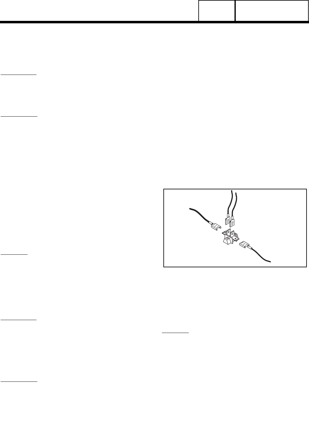
b. Connect the positive (+) test lead to Wire 14 at the 4-tab
terminal block in the control panel, see Figure 17.
Connect the negative (-) test lead to frame ground. While
observing the meter, set the AUTO-OFF-MANUAL
switch to MANUAL. Battery voltage should be measured.
Figure 17. 4-Tab Terminal Block
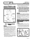
5. Set the VOM to it’s “R x 1” scale.
6. Disconnect Wire 0 from the Fuel Solenoid (FS). Connect
one test lead to Wire 0 and the other test lead to a clean
frame ground. CONTINUITY should be measured.
RESULTS:
1. If the engine cranks but does not start and battery voltage
was NOT measured in Step 3, replace the circuit board.
2. If the engine cranks and battery voltage was measured
in Step 3, but there was no battery voltage in Step 4(a),
repair or replace Wire 14 between 4-tab terminal block
and the Fuel Solenoid (FS).
3. If the engine cranks and battery voltage was measured
in step 3 and no battery voltage is measured in step 4b,
repair or replace Wire 14 between the J1 connector on
the circuit board and the 4-tab terminal block.
DC CONTROL
Page 4.4-10