


SECTION 2.4
DIAGNOSTIC TESTS
PART 2
AC GENERATORS
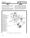
14. Connect one meter test lead to Pin 10 (wire 4) of the
C2 connector (male side). Connect the other meter test
lead to Wire 4 removed from the Voltage regulator.
CONTINUITY should be measured. If INFINITY is
measured repair or replace wire 4 between the C2
connector and the voltage regulator.
RESULTS:
1. Repair, replace or reconnect wires as necessary.
2. Replace any damaged slip rings or brush holder.
3. Clean and polish slip rings as required.
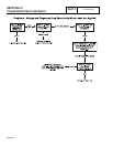
TEST
10
-
TEST
ROTOR
ASSEMBLY
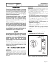
DISCUSSION:
A rotor having completely open windings will cause loss of
excitation current flow and, as a result, generator AC output
voltage will drop to "residual" voltage. A "shorted" rotor
winding can result in a low voltage condition.
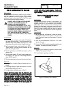
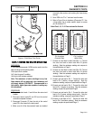
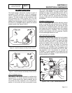
PROCEDURE:
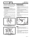
I. Disconnect the brush wires or remove the brush holder,
to prevent interaction.
2. Set a VOM to its "R x 1" scale and zero the meter.
3. Connect the positive (+) VOM test lead to the positive
(+) rotor slip ring (nearest the rotor bearing); and the
common (-) test lead to the negative (-) slip ring. The
meter should read approximately 10-20 ohms. Compare
to “Specifications,” Page 1.
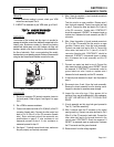
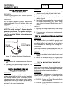
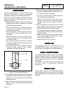
4. Now, set the VOM to a high resistance scale (such as
"R x 10,000" or "R x 1K"). Again, zero the meter.
5. Connect the positive (+) VOM test lead to the positive
(+) slip ring and the common (-) test lead to a clean
frame ground. The meter should indicate INFINITY.
RESULTS:
1. Replace rotor assembly if it is open or shorted.
2. If rotor tests good, perform “Insulation Resistance Test”
on Page 1.4-6.
NOTE: Be sure to read Section 1.4, "Testing, Cleaning
and Drying", carefully. If the rotor tests good, try
performing an insulation resistance test. Clean and dry
the rotor if it fails that test. Then, repeat the test. If the
rotor fails the second insulation resistance test, it
should be replaced.
Figure 8. The Rotor Assembly
TEST
11
-
CHECK
AC
OUTPUT
FREQUENCY
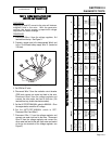
DISCUSSION:
The generator AC frequency is proportional to the operating
speed of the rotor. The 2-pole rotor will supply a 60 Hertz
AC frequency at 3600 rpm. The unit's AC output voltage is
proportional to the AC frequency. For example, a unit rated
240 volts (line-to-line) will supply that rated voltage (plus or
minus 2 percent) at a frequency of 60 Hertz. If, for any
reason, the frequency should drop to 30 Hertz, the line-to-
line voltage will drop to a matching voltage of 120 volts AC.
Thus, if the AC voltage output is high or low and the AC
frequency is correspondingly high or low, the engine speed
governor may require adjustment.
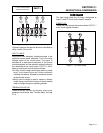
PROCEDURE:
1. Connect an accurate AC frequency meter across the
Wires 11 and 44 terminals of the generator main line
circuit breaker (see Figure 1, Page 2.4-1).
2. Start the engine, let it stabilize and warm up at no-load.
3. When engine has stabilized, read the frequency meter.
The no-load frequency should be about 61-63 Hertz.
RESULTS:
1. If the AC frequency is high or low, go on to Test 12.
2. If frequency is good, but voltage is high or low, go to
Test 13.
3. If frequency and voltage are both good, tests may be
discontinued.
TEST
12
-
CHECK
AND
ADJUST
ENGINE
GOVERNOR
DISCUSSION:
The generator AC frequency output is directly proportional
to the speed of the rotor. A two-pole rotor (having a single
north and a single south magnetic pole) will produce an AC
frequency of 60 hertz at 3600 RPM.
The generator is equipped with a "voltage over frequency"
type AC voltage regulator. The units AC output voltage is
Page 2.4-8