


SECTION 3.1
DESCRIPTION & COMPONENTS
V-TYPE PREPACKAGED
TRANSFER SWITCHES
PART 3
Page 3.1-2
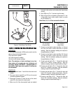
TRANSFER
MECHANISM
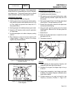
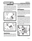
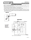
The 2-pole transfer mechanism consists of a pair of
moveable LOAD contacts, a pair of stationary
UTILITY contacts, and a pair of stationary STANDBY
contacts. The load contacts can be connected to the
utility contacts by a utility closing coil; or to the
standby contacts by a standby closing coil. In
addition, the load contacts can be actuated to either
the UTILITY or STANDBY side by means of a manual
transfer handle. See Figures 2 and 3.
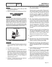
Figure 2. Load Connected to Utility Power Source
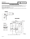
Figure 3. Load Connected to Standby Power Source
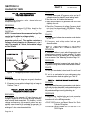
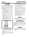
UTILITY CLOSING COIL C1:
See Figure 4. This coil is energized by rectified utility
source power, to actuate the load contacts to the
UTILITY power source side. When energized, the coil
will move the main contacts to an "overcenter"
position. A limit switch will then be actuated to open
the circuit and spring force will complete the
retransfer to STANDBY. A bridge rectifier, which
changes the utility source alternating current (AC) to
direct current (DC), is sealed in the coil wrappings. If
coil or bridge rectifier replacement becomes
necessary, the entire coil and bridge assembly should
be replaced.
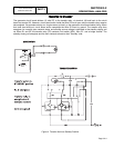
STANDBY CLOSING COIL C2:
Coil C2 is energized by rectified standby source
power, to actuate the load contacts to their "Standby"
source side. Energizing the coil moves the load
contacts to an overcenter position; limit switch action
then opens the circuit and spring force will complete
the transfer action to "Standby". This coil’s bridge
rectifier is also sealed in the coil wrappings. Replace
the coil and bridge rectifier as a unit.
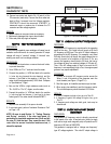
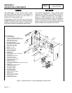
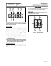
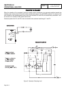
LIMIT SWITCHES XA1 AND XB1:
Switches are mechanically actuated by load contacts
movement. When the load contacts are connected to
the utility contacts, limit switch XA1 opens the utility
circuit to utility closing coil C1 and limit switch XB1
closes the standby circuit to standby closing coil C2.
The limit switches "arm" the system for retransfer
back to UTILITY when the load contacts are
connected to the STANDBY side. Conversely, when
the load contacts are connected to the UTILITY side,
the switches "arm" the system for transfer to
STANDBY. An open condition in limit switch XA1 will
prevent retransfer to "Utility". An open switch XB1 will
prevent transfer to STANDBY.
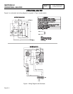
Figure 4. The "V-Type" Transfer Mechanism