


SECTION 4.4
DIAGNOSTIC TESTS
PART 4
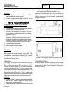
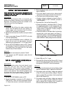
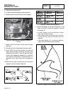
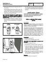
4. Tighten both mounting screws.
5. To remove the thickness gauge, rotate the flywheel.
6. Repeat the above procedure for the second magneto.
Figure 23. Setting Ignition Magneto (Armature)
Air Gap
7. Repeat Test 55 and check for spark across the spark
tester gap.
8. If air gap was not out of adjustment, test ground wires.
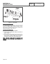
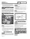
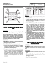
9. Set the VOM to the diode test position. The meter will
display forward voltage drop across the diode. If the
voltage drop is less than 0.7 volts, the meter will “Beep”
once as well as display the voltage drop. A continuous
tone indicates CONTINUITY (shorted diode). An
incomplete circuit (open diode) will be displayed as
“OL.”
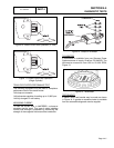
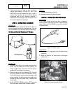
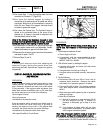
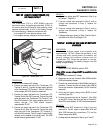
10.Disconnect the engine wire harness from the ignition
magnetos and stud connector (Figure 24).
Figure 24. Engine Ground Harness
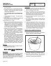
Figure 25. Diode Failure Diagnosis
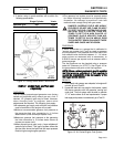
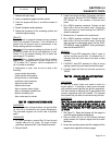
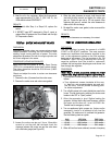
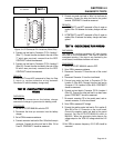
11.Connect the positive (+) test lead to Connector ”A” (as
shown in Figure 26). Connect the negative (-) test lead
to Connector “B.”
a.If meter Beeps once and displays voltage
drop, then the diode is good.
b.If the meter makes a continuous tone, the diode
is bad (shorted) and the harness must be
replaced.
c. If the meter displays OL, the diode is defective
(open) and the harness must be replaced.
Figure 26. Engine Ground Harness Test Points
DC CONTROL
Page 4-4.14