


SECTION 4.4
DIAGNOSTIC TESTS
6. Connect one meter test lead to Wire 351 (previously
removed from SW2). Connect the other meter test lead
to Pin Location J3 (Wire 351). CONTINUITY should be
measured.
7. Connect one meter test lead to Wire 351 (previously
removed from SW2). Connect the other meter test lead
to the ground terminal. INFINITY should be measured.
8. Connect one meter test lead to Wire 0 (previously
removed from SW2). Connect the other meter test lead to
the ground terminal. CONTINUITY should be measured.
RESULTS:
1. If the Set Exercise Switch (SW2) fails Step 3 or Step 4,
replace the switch.
2. If CONTINUITY was NOT measured in Step 6, OR if it
WAS measured in Step 7, repair or replace Wire 351
between SW2 and Connector J2.
3. If CONTINUITY was NOT measured in Step 8, repair or
replace Wire 0 between SW2 and the ground terminal.
TEST
74
-
CHECK
REMOTE
START
WIRING
(IF
EQUIPPED)
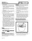
DISCUSSION:
On some earlier models a remote start connection
was available. If these two wires are connected
together while the generator is in AUTO, the
generator will start.
PROCEDURE:
1. Set the AUTO-OFF-MANUAL switch to OFF.
2. Set a VOM to measure resistance.
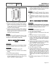
3. Disconnect the 17-pin connector (J1) from the circuit
board.
4. If the remote start connections have been used,
disconnect the customer wires from the terminal
connector at Wire 178 and Wire 183.
5. Connect one meter test lead to Wire 178 at the terminal
connector. Connect the other meter test lead to Wire 183
at the terminal connector. INFINITY should be measured.
6. If the remote start connections have been used, connect
the meter test leads across customer supplied wiring. If
CONTINUITY is measured, customer supplied circuit is
causing startup.
RESULTS:
1. If CONTINUITY was measured in Step 5, a short exists
between Wire 178 and Wire 183. Repair or replace
Wire 178 and/or Wire 183 between terminal connector
and SW1.
TEST
75
-
CHECK
BATTERY
VOLTAGE
CIRCUIT
DISCUSSION:
If the 15 amp fuse blows immediately after
replacement, Wire 15 should be checked for a fault.
PROCEDURE:
1. Set the AUTO-OFF-MANUAL switch to OFF.
2. Disconnect the 17-pin connector (J1) from the circuit
board.
3. Set a VOM to measure resistance.
4. Disconnect Wire 15 from the fuse holder (F1).
5. Connect one meter test lead to Wire 15 (removed from
fuse holder in previous step). Connect the other meter
test lead to the ground terminal. INFINITY should be
measured.
RESULTS:
1. If CONTINUITY was measured in Step 5, repair or
replace Wire 15 between the fuse holder (F1) and SW1,
or between SW1 and Connector J1.
2. If INFINITY was measured in Step 5, replace the circuit
board and retest.
TEST
76
-
CHECK
CRANKING
AND
RUNNING
CIRCUITS
DISCUSSION:
This test will check all of the circuits that are HOT
with battery voltage and which could cause the F1
Fuse to blow.
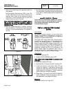
PROCEDURE:
1. Set a VOM to measure resistance.
2. Disconnect the 17-pin connector (J1) from the circuit board.
3. Connect one meter test lead to the ground terminal.
Connect the other meter test lead to each of the
following J1 Connector pin locations:
DC CONTROL
PART 4
Page 4.4-23