


SECTION 4.4
DIAGNOSTIC TESTS
PART 4
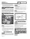
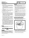
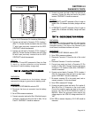
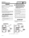
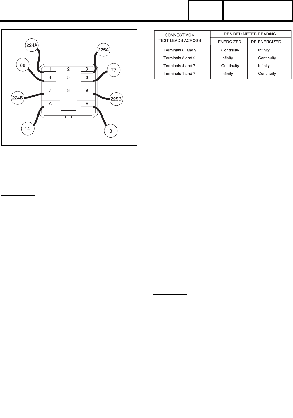
Figure 33. Battery Charge Relay Test Points
TEST
67
-
CHECK
BATTERY
CHARGE
RELAY
(BCR)
DISCUSSION:
The battery charge relay is used to switch the AC
source delivered to the battery charger. When the
BCR is de-energized, the Normally Closed (NC)
contacts deliver AC power from the transformer.
When the BCR is energized by Wire 14, the Normally
Open (NO) contacts close and battery charge winding
AC source is delivered to the battery charger.
PROCEDURE:
1.See Figure 33. Disconnect all wires from the battery
charge relay, to prevent interaction.
2.Set a VOM to its "R x 1" scale and zero the meter.
3. Follow the chart below and test each set of contacts.
Connect the VOM test leads to the relay terminals
indicated in the chart provided below.
4. To energize or de-energize the relay. Connect a jumper
wire to a positive (+)12VDC source and to relay
Terminal "A". Connect a jumper wire to the negative (-)
12VDC source and to relay Terminal "B". The relay will
ENERGIZE. Disconnect the positive jumper from
Terminal "A" of the relay and the relay will DE-
ENERGIZE.
RESULTS:
1. Replace the battery charge relay if it fails any of the
steps in this chart.
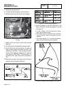
2. If the BCR tests good, but still does not function during
generator operation, check Wire 14 and Wire 0
connected to the BCR.
a.Set a VOM to measure DC volts. Disconnect
Wire 14 from BCR Terminal A. Connect the
positive (+) test lead to Wire 14. Connect the
negative (-) test lead to a clean frame ground.
Set the AUTO-OFF-MANUAL switch to
MANUAL. Battery voltage should be measured.
If battery voltage is not measured, repair or
replace Wire 14 between the BCR and the 4-tab
terminal block.
b.If voltage was measured in a, set the VOM to
measure resistance. Disconnect Wire 0 from
BCR Terminal B. Connect one test lead to Wire
0. Connect the other test lead to a clean frame
ground. CONTINUITY should be measured. If
CONTINUITY was not measured, repair or
replace Wire 0 between the BCR and the ground
terminal.
TEST
68
-
CHECK
BATTERY
CHARGE
WINDING
HARNESS
DISCUSSION:
This test will check the continuity of Wire 66 and Wire
77 between Connector C2 and the battery charge
relay.
PROCEDURE:
1. Disconnect Connector C2 from the side of the control
panel.
2. Disconnect Wire 66 from Terminal 6, and Wire 77 from
Terminal 4 of the BCR.
3. Set a VOM to measure resistance.
DC CONTROL
Page 4.4-20