


SECTION 4.2
OPERATIONAL ANALYSIS
PART 4
DC CONTROL
UTILITY
VOLTAGE
DROPOUT
AND
ENGINE
CRANKING
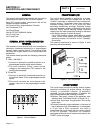
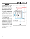
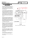
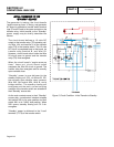
After fifteen (15) seconds and when the circuit
board’s 15-second timer has timed out, if
"Utility" voltage is still below 60 percent of
nominal, circuit board action will energize the
circuit board’s crank and run relays (K1 and
K2) simultaneously.
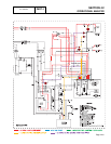
The crank relay (K1) will remain energized for
about 15 seconds on the first crank cycle. The
relay will then de-energize for 7 seconds and
will again energize. This time it will remain
energized for 7 seconds. Thus, the engine will
crank cyclically for 7 second crank-rest
cycles. This cyclic cranking will continue until
either the engine starts or until about ninety
(90) seconds of crank-rest cycles have been
used up.
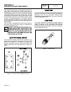
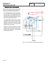
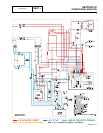
When the crank relay (K1) is energized, circuit
board action delivers 12 volts DC to a starter
contactor relay (SCR), via Wire 56. When the
SCR energizes, its contacts close and battery
power is delivered to a starter contactor (SC).
When the SC energizes, its contacts close
and battery power is delivered to the starter
motor (SM).The engine cranks.
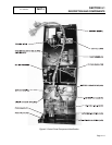
When the circuit board’s run relay (K2)
energizes, 12 volts DC is delivered to a fuel
solenoid (FS), via Wire 14. The fuel solenoid
(FS) energizes open and fuel is available to
the engine. Wire 14 also energizes the
hourmeter for operation (if so equipped) .
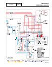
Wire 14 energizes the battery charge relay
(BCR), which will allow the BCR to power the
battery charger.
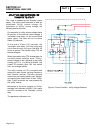
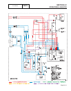
As the engine cranks, magnets on the engine
flywheel induce a high voltage into the engine
ignition modules (IM1/IM2). A spark is
produced that jumps the spark plug
(SP1/SP2) gap.
During cranking, Wire 4 supplies 2-3 VDC (8-
9 VDC isolated) to the rotor for field flash.
With ignition and fuel flow available the
engine can start.
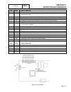
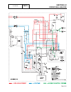
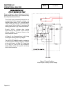
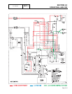
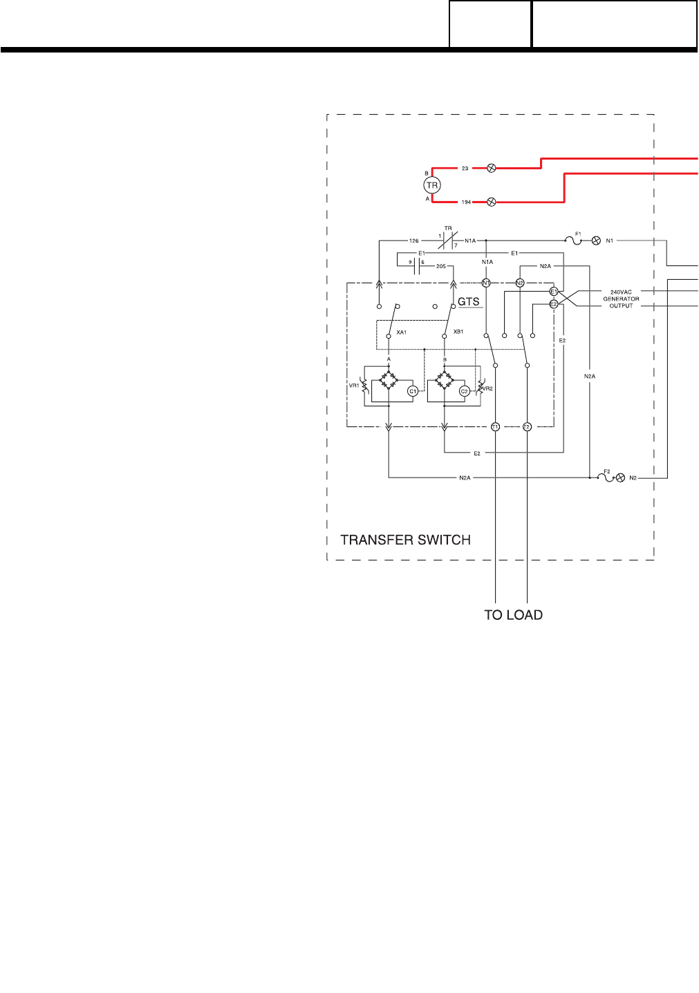
Figure 3. Circuit Condition - Engine Cranking
Page 4.2-5