


Section 7
DIAGNOSTIC TESTS
RESULTS:
1. If Choke Plate is binding in Step 1, repair or
replace binding Choke Plate. If Bi-Metal Heater
Assembly tests good, go to Test 32.
2. If continuity was not measured in Step 3, repair or
replace Wire 14 between the 4-tab Connector and
Connector 3.
3. If the resistance value is incorrect in the Short to
Ground step, or the Bi-Metal Heater Assembly
does not function with voltage present, replace
the Bi-Metal Heater Assembly.
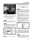
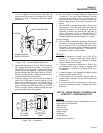
TEST 41 – CHECK LPG FUEL SOLENOID
DISCUSSION:
If the LPG Fuel Solenoid (FS) fails to open, fuel will
not be available to the engine and it will not start.
PROCEDURE:
1.
Place one hand on the top of the LPG Fuel
Solenoid. Activate the Fuel Prime Switch. You
should be able to feel as well as hear the solenoid
energize. If solenoid energizes discontinue testing.
2. Set VOM to measure resistance. Disconnect Wire
0 from the LPG Fuel Solenoid. Connect one meter
test lead to Wire 0. Connect the other test lead to
a clean frame ground. “Continuity” should be mea-
sured. Reconnect Wire 0 to LPG shut off valve.
SHORT TO GROUND:
Set VOM to measure resistance. Disconnect Wire 14A
from the LPG Fuel Solenoid. Connect one meter test
lead to LPG Fuel Solenoid. terminal that Wire 14A
was just removed from. Connect the other meter test
lead to a clean frame ground. LPG Fuel Solenoid.
Coil resistance of approximately 30-32 ohms Should
be measured. Current draw of the LPG Fuel Solenoid
at nominal voltage Is approximately 380 milliamps or
0.380 amps.
RESULTS:
1. If the solenoid energized in Step 1, proceed to
Test 29.
2. If “Continuity” was not measured in Step 2 repair
or replace Wire 0 between the LPG Fuel Solenoid
(FS) and the Ground Terminal (GRD1) in the con-
trol panel.
3. If “Continuity” was measured in Step 2, repair or
replace the Fuel Solenoid (FS).
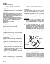
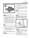
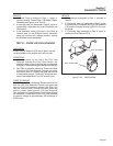
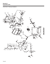
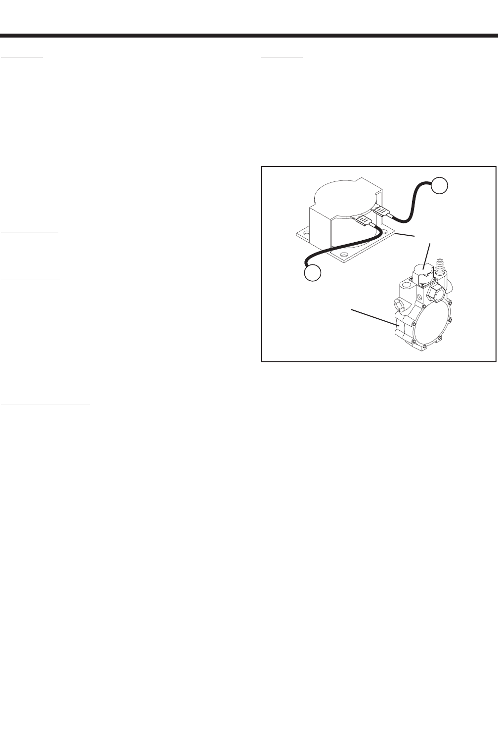
FUEL SOLENOID
FUEL REGULATOR
0
241
Figure 7-49. – Fuel Solenoid
Page 63