


Section 7
DIAGNOSTIC TESTS
4 0
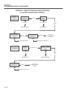
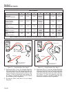
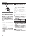
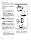
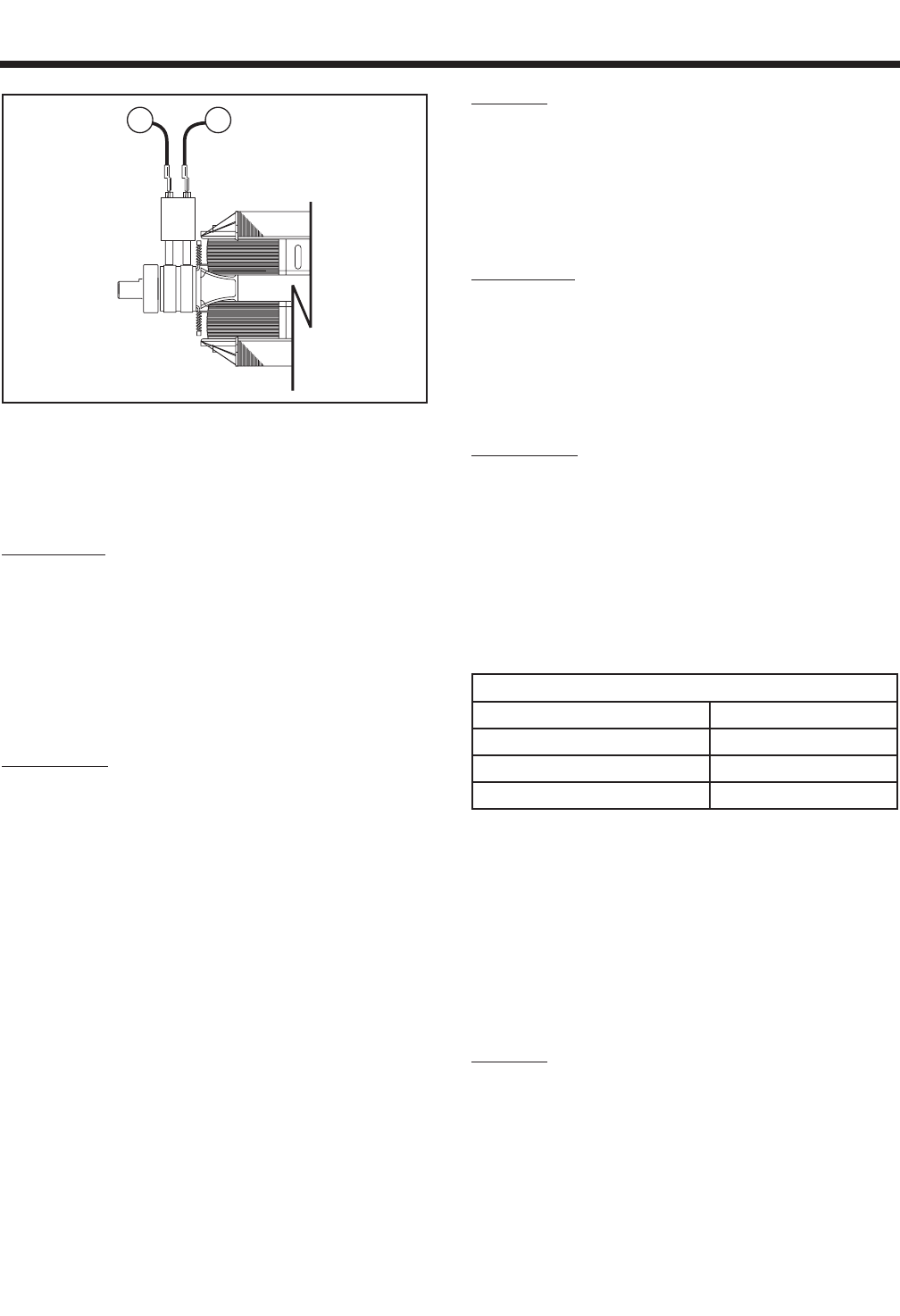
Figure 7-10. – Brush Leads
TEST 9 – CHECK BRUSHES & SLIP RINGS
DISCUSSION:
Brushes and slip rings are made of special materials
that will provide hundreds of hours of service with little
wear. However, when the generator has been idle for
some time, an oxide film can develop on the slip rings.
This film acts as an insulator and impedes the flow of
excitation current to the Rotor.
If Test 4 resulted in less than one-half rated output
voltage, it is possible that the brushes and slip rings
are at fault.
PROCEDURE:
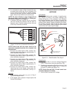
1. Gain access to the brushes and slip rings.
2. Remove Wire 4 from the positive (+) brush termi-
nal.
3. Remove the ground wire (Wire 0) from the nega-
tive (-) brush.
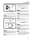
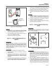
4. Remove the brush holder, with brushes.
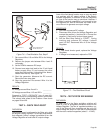
5. Inspect the brushes for excessive wear, damage,
cracks, chipping, etc.
6. Inspect the brush holder, replace if damaged.
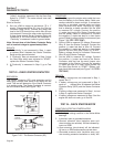
7. Inspect the slip rings.
a. If slip rings appear dull or tarnished they may be
cleaned and polished with fine sandpaper. DO
NOT USE ANY METALLIC GRIT TO CLEAN
SLIP RINGS. (A 400 grit wet sandpaper is rec-
ommended).
b. After cleaning slip rings, blow away any sandpa-
per residue.
RESULTS:
1. Replace bad brushes. Clean slip rings, if neces-
sary.
2. If brushes and rings are good, go to Test 10.
TEST 10 – CHECK ROTOR ASSEMBLY
DISCUSSION:
During the “Test 4 – Fixed Excitation Test,” if AC out-
put voltage did not come up to about one-half rated
volts, one possible cause might be a defective Rotor.
The Rotor can be tested for an open or shorted condi-
tion using a volt-ohm-milliammeter (VOM).
Also see Chapter Three, “INSULATION RESISTANCE
TESTS”.
PROCEDURE:
Gain access to the brushes and slip rings. Disconnect
Wire 4 and Wire 0 from their respective brushes and
remove the brush holder. Then, test the Rotor as fol-
lows:
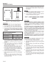
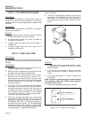
1. Set a VOM to its “Rx1” scale and zero the meter.
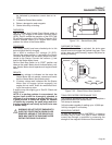
2. Connect the positive (+) meter test lead to the
positive (+) slip ring (nearest the Rotor bearing).
Connect the common (-) test lead to the nega-
tive (-) slip ring. Read the resistance of the Rotor
windings, in OHMS.
ROTOR RESISTANCE *
MODEL OHMS
RV45 5410/5411 13.4Ω
RV55 5412/5413 14.88Ω
RV65 5414/5415 10.81Ω
* Resistance values In ohms at 20° C. (68° F.).
Actual readings may vary depending on ambient
temperature. A tolerance of plus or minus 5% is
allowed.
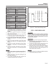
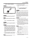
3. Set the VOM to its “Rx1 K” or “Rx10,000” scale
and zero the meter.
4. Connect the positive (+) meter test lead to the
positive (+) slip ring, the common (-) test lead to a
clean frame ground (such as the Rotor shaft). The
meter should read “Infinity”.
RESULTS:
1. Replace the Rotor if it fails the test.
2. If Rotor checks good, perform “Insulation
Resistance Test,” on Page 14.
Page 42