


70
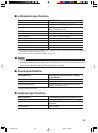
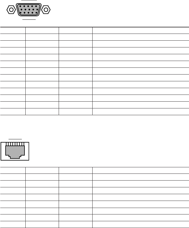
■ Connector specifications
The pin assignments and signal names of each connector are as follows:
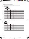
● CRT connector
51
15
10 6
11
Pin No.
1
2
3
4
5 to 8
9
10
11
12
13
14
15
Signal name
RED
GREEN
BLUE
ID2
GND
VCC
GND
ID0
ID1 (SDA)
HSYNC
VSYNC
SCL
I/O
Output
Output
Output
I/O
—
—
—
I/O
I/O
Output
Output
I/O
Description
Red output
Green output
Blue output
Not connected
Ground
Power
Ground
Not connected
DDC data
Output Horizontal synchronizing signal
Output Vertical synchronizing signal
DDC clock
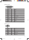
● LAN connector (100BASE-TX/10BASE-T)
Pin No.
1
2
3
4
5
6
7
8
Signal name
TD+
TD-
RD+
NC
NC
RD-
NC
NC
I/O
Output
Output
Input
—
—
—
—
—
Description
Transmit data+
Transmit data-3
Receive data+
Not connected
Not connected
Receive data-7
Not connected
Not connected
18
11-DP8 (67-75) 3/2/01, 2:33 PM70