


Maintenance
G005278
1
2
2
3
3
4
4
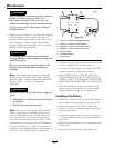
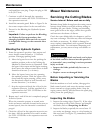
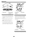
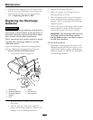
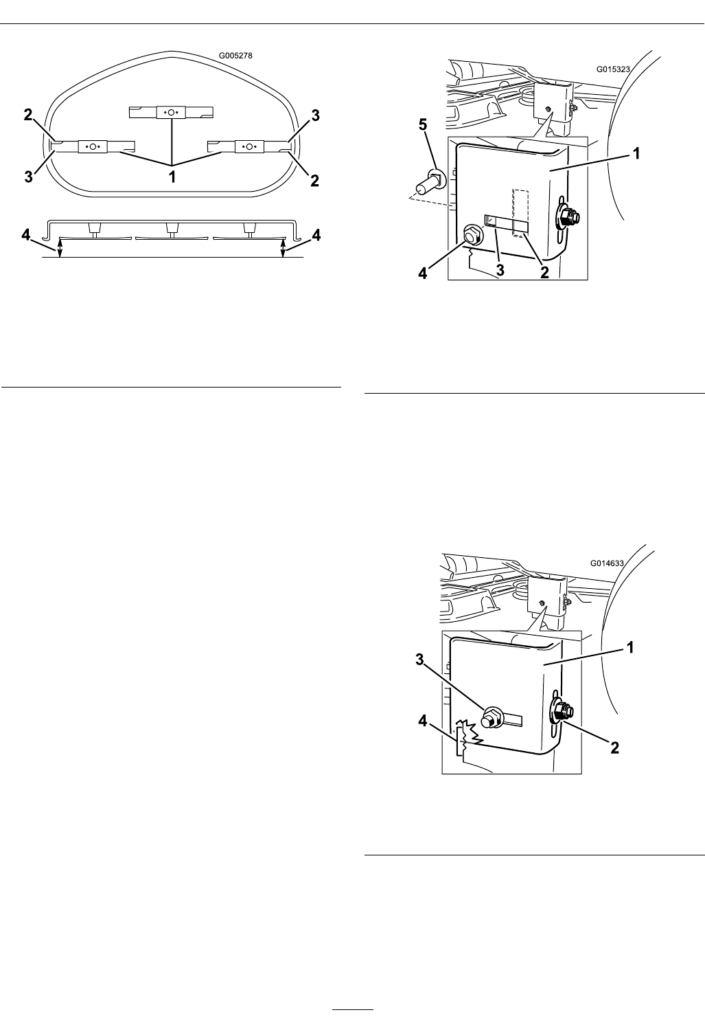
Figure 48
50 Inch Decks
1. Blades side to side
3. Outside cutting edges
2. Sail area of blade 4. Measure from the tip
of the blade to the at
surface here
5. Measure between the outside cutting edges and
the at surface (Figure 47 and Figure 48). If both
measurements are not within 3/16 inch (5 mm),
an adjustment is required; continue with this
procedure.
6. Support the weight of mower deck by placing
wood blocks under the edges of the deck.
Note: Avoid placing the supports under any
anti-scalp rollers if present on the deck.
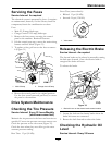
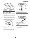
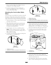
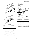
7. Move to the left side of the machine. Remove
the side carriage bolt and locking nut from the
xed position and install it into the rear, slotted
position and leave it slightly loose (
Figure 49).
G015323
1
2
3
4
5
Figure 49
1. Hanger bracket
4. Side locking nut
2. Slotted adjustment
position
5. Side carriage bolt
3. Fixed position
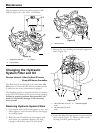
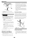
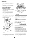
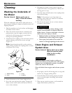
8. Loosen the side locking nut on the hanger bracket
just enough to allow the hanger to be adjusted
(Figure 50). Use the notches on the welded
bracket to measure the amount of adjustment.
Each notch surface is equivalent to 1/16 of an
inch. Adjust the height of the mower deck to the
desired height.
G014633
1
2
3
4
Figure 50
1. Hanger bracket
3. Side locking nut
2. Rear locking nut 4. Adjustment notches
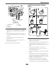
9. Stop the deck at the adjusted position and tighten
the side locking nut on the hanger bracket to hold
46