


Maintenance
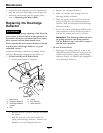
Figure 45
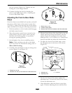
1. Sharpen at original angle
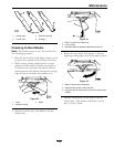
2. Check the balance of the blade by putting it on a
blade balancer (Figure 46). If the blade stays in a
horizontal position, the blade is balanced and can
be used. If the blade is not balanced, le some
metal off the end of the sail area only (Figure 46).
Repeat this procedure until the blade is balanced.
Figure 46
1. Blade 2. Balancer
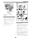
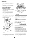
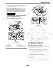
Installing the Blades
1. Install the blade onto the spindle shaft (Figure 44).
Important: The curved part of the blade
must be pointing upward toward the inside of
the mower to ensure proper cutting.
2. Hold the blade end using a rag or thickly-padded
glove (or place a wrench on the top sheave nut).
Apply lubricant to the threads of the blade bolt
as needed to prevent seizing. Copper based
anti-seize is preferable. Grease is an acceptable
substitute. Install the washer and blade bolt and
washer assembly.
3. Torque the blade bolt to 35-65 ft-lb (47-88 N-m).
WARNING
Incorrect installation of the blade or
components used to retain the blade cause
the blade to come loose and could seriously
injure or kill you or bystanders.
Always install the original Exmark blades,
washers and blade bolts as shown.
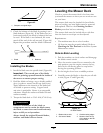
Leveling the Mower Deck
Check to ensure the mower deck is level any time
you install the mower or when you see an uneven cut
on your lawn.
The mower deck must be checked for bent blades
prior to leveling; any bent blades must be removed
and replaced. Refer to the Checking for Bent
Blades procedure before continuing.
The mower deck must be leveled side-to-side rst
then the front to rear slope can be adjusted.
Requirements:
• The machine must be on a level surface.
• All four tire must be properly inated. Refer to
Checking the Tire Pressure in the Drive System
Maintenance section.
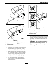
Side-to-Side Leveling
1. Park the machine on a level surface and disengage
the blade control switch.
2. Move the motion control levers outward to the
park position, stop the engine, remove the key,
and wait for all moving parts to stop before
leaving the operating position.
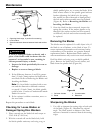
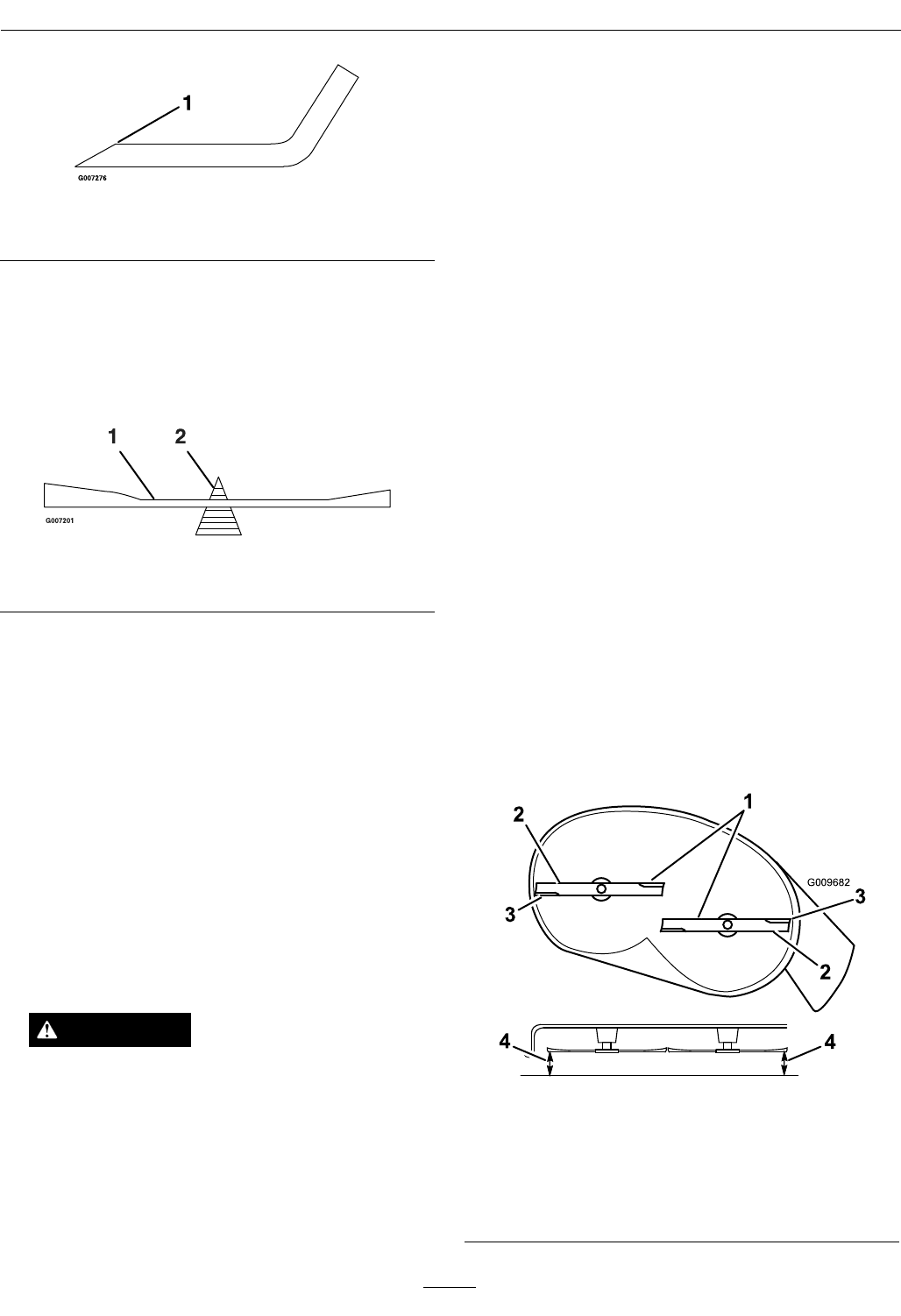
3. Set the height-of-cut lever to middle position.
4. Carefully rotate the blades so that they are all side
to side (
Figure 47 and Figure 48).
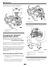
G009682
1
2
2
3
3
4
4
Figure 47
42 Inch Decks
1. Blades side to side
3. Outside cutting edges
2. Sail area of blade 4. Measure from the tip
of the blade to the at
surface here
45