


Operation
Operation
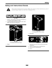
Controls
Note: Become familiar with all of the controls in
Figure 3 and Figure 4 before you start the engine and
operate the machine.
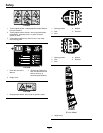
Ignition Switch
Located on control panel.
The ignition switch is used to start and stop the
engine. The switch has three positions “OFF”,
“RUN” and “START” (
Figure 4). Insert key into
switch and rotate clockwise to the “ON” position.
Rotate clockwise to the next position to engage the
starter (key must be held against spring pressure in
this position).
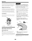
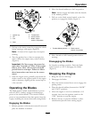
Figure 4
1. Ignition switch
3. Choke control
2. Throttle lever 4. Blade control switch
(power take-off)
Note: Brake must be engaged (motion control levers
out) and PTO switch “OFF” to start engine. (It is
not necessary for the operator to be in the seat to
start the engine.)
Turning the key to the Off position will stop the
engine; however, always remove the key when leaving
the machine to prevent someone from accidentally
starting the engine.
Blade Control Switch (Power
Take-Off)
Located on the control panel.
The blade control switch, represented by a power
take-off (PTO) symbol, engages and disengages
power to the mower blades (see
Figure 4).
Pull out on the blade control switch to “On” to
engage the blades.
Push the blade control switch to “Off ” to disengage
the blades.
Throttle Lever
Located on control panel.
The throttle is used to control engine speed. Moving
throttle lever forward will increase engine speed and
moving throttle lever to the rear will decrease engine
speed. Moving the throttle forward until it stops is
full throttle (see
Figure 4).
Choke Control
The choke is used to aid in starting a cold engine.
Pulling up on the choke control will put the choke in
the “ON” position and pushing down the control will
put the choke in the “OFF” position. Do Not run a
warm engine with the choke in the “ON” position.
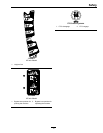
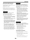
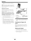
Motion Control Levers and Parking
Brake Position
The motion control levers located on each side of
the seat (Figure 3).
The motion control levers are speed sensitive controls
of independent wheel motors. Moving a lever
forward or backward turns the wheel on the same side
forward or in reverse; wheel speed is proportional to
the amount the lever is moved. Moving the control
levers outward from the center position engages the
parking brake on the drive wheels. Always position
the motion control levers into the parking brake
position when you stop the machine or leave it
unattended. The unit must be tied down and brake
engaged when transporting.
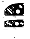
Deck Height Adjustment Lever
Located below the RH motion control lever
(Figure 3).
17