


NOTE:
I
f you have a dual input analyzer, you can reapply power at this point. The initial reading
from the other sensor will be momentarily zero. After about 60 seconds the reading will
reach its final value.
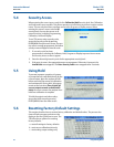
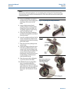
3. Using a small Phillips screwdriver,
remove the two screws holding the
top flange of the sensor to the
body.
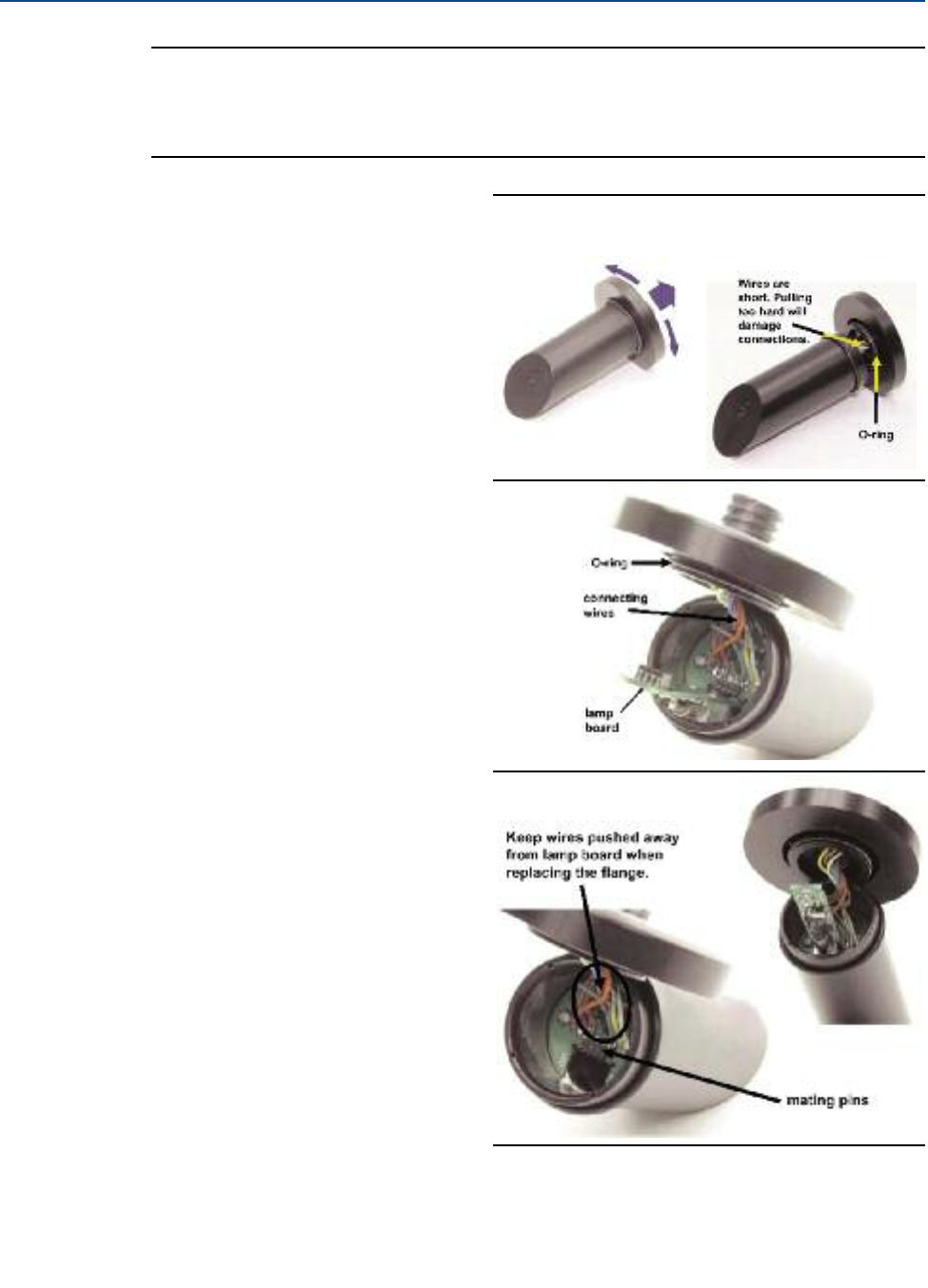
4. Using a slight back and forth
twisting motion carefully pull the
flange from the sensor body. You
are pulling against a single O-ring
seal. Don’t pull too hard.
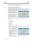
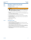
5. Using your thumb and forefinger,
remove the lamp/LED circuit board
from the sensor.
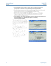
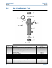
6. Insert the replacement board in the
sensor and push the socket on the
replacement board into the mating
pins in the sensor.
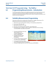
7. Place the desiccant package in the
sensor body.
8. Orient the flange so that the screw
holes line up with the holes in the
sensor body. Push the flange back
on the sensor body and replace the
screws. Don’t let wires push on
lamp board. It may be necessary to
turn the flange a small amount
until the holes line up.
9. Place the sensor in the calibration
cup and reconnect the cable.
10. Calibrate the sensor using either
slope or standard calibration
(Section 6.2 or 6.3). Do not use
grab calibration. Failure to calibrate
the sensor may reduce the life of
the sensor. See Sections 8.2.5 and
8.2.6.
28 Maintenance
Instruction Manual Clarity II T56
PN-51-T56 May 2012
Fig. 8-1 Replacing the Lamp/LED Board
Step 4
Step 5
Step 6