


Instruction Manual Clarity II T56
PN-51-T56 May 2012
8 Ordering Information
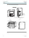
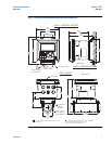
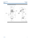
2.3 Installation – Debubbler Assembly
See Figure 2-3 for installation.
Connect the sample line to the inlet fitting. The fitting accepts 1/4-inch OD tubing. See Section
2.6 for recommended installation of the sample port.
Attach a piece of 3/8 inch ID soft tubing to the drain fitting. The debubbler must drain to atmos-
phere.
NOTE:
During operation, the debubbler is under pressure. A 0.040 inch (1 mm) orifice in the
outlet provides the pressure. Back pressure helps prevent outgassing, which can lead to
bubbles accumulating on the sensor face resulting in erroneous readings. DO NOT
EXCEED 30 psig (308 kPa abs) inlet pressure.
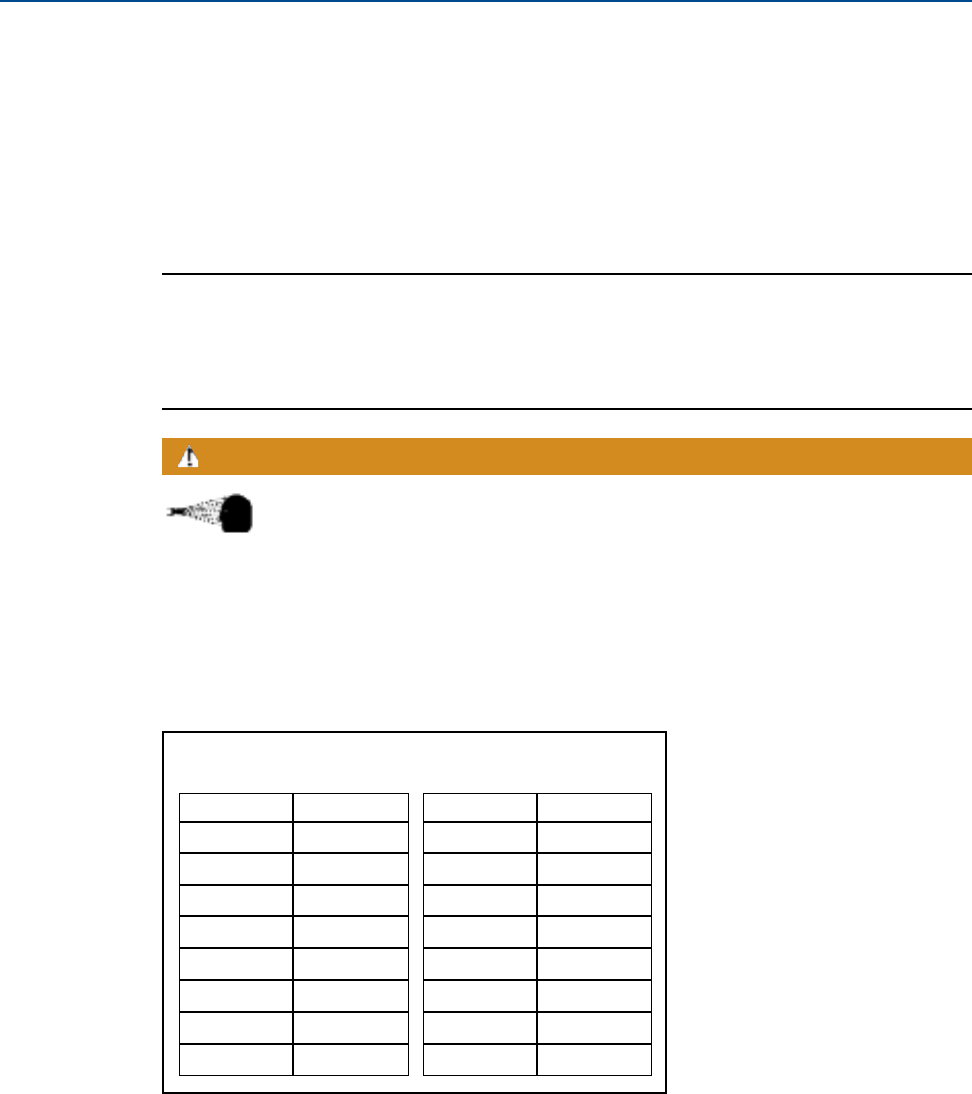
The amount of pressure in the debubbler can be estimated from the flow rate. See Table 2-1.
To control and monitor sample flow, a valved rotameter with fittings is available (PN 24103-00).
Attach the rotameter to the debubbler outlet. The rotameter can also be used to increase back
pressure on the debubbler if additional pressure is needed to prevent outgassing.
Before removing the sensor, be absolutely certain that the process pressure
is reduced to 0 psig and the process temperature is lowered to a safe level!
WARNING
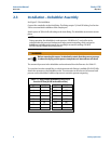
TABLE 2-1. Approximate debubbler pressure as a
function of flow (0.040 inch outlet orifice)
mL/min kPa abs
100 110
200 120
300 140
400 160
500 190
600 240
700 280
800 340
gph psig
21
43
68
8 14
10 21
11 26
12 31
––