


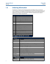
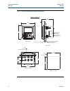
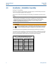

3.2 Preparing Conduit Openings
There are six conduit openings in all configurations of T56. (Note that four of the openings will
b
e fitted with plugs upon shipment.)
Conduit openings accept 1/2-inch conduit fittings or PG13.5 cable glands. To keep the case water-
tight, block unused openings with NEMA 4X or IP65 conduit plugs.
NOTE:
Use watertight fittings and hubs that comply with your requirements. Connect the conduit hub
to the conduit before attaching the fitting to the analyzer.
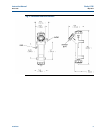
3.3 Preparing Sensor Cable
The T56 is intended for use with all Rosemount Analytical sensors. Refer to the sensor
installation instructions for details on preparing sensor cables.
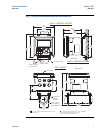
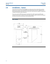
3.4 Power, Output, and Sensor Connections
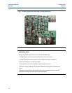
3.4.1 Power wiring
Two Power Supplies are offered for the T56:
a. 24VDC (20 – 30V) Power Supply (-02 ordering code)
b. 85 – 265 VAC Switching Power Supply (-03 ordering code)
AC mains leads and 24VDC leads are wired to the Power Supply board which is mounted vertically
on the left side of the main enclosure cavity. Each lead location is clearly marked on the Power Supply
board. Wire the power leads to the Power Supply board using the lead markings on the board.
The grounding plate is connected to the earth terminal of the -03 (85-265VAC) power supply.
The green colored screws on the grounding plate are intended for connection to some sensors
to minimize radio frequency interference. The green screws are not intended to be used for
safety purposes.
3.4.2 Current output wiring
All instruments are shipped with four 4-20mA current outputs. Wiring locations for the outputs
are on the Main board which is mounted on the hinged door of the instrument. Wire the output
leads to the correct position on the Main board using the lead markings (+/positive, -/negative)
on the board. Male mating connectors are provided with each unit.
3.4.3 Alarm relay wiring
Four alarm relays are supplied with the switching power supply (85 to 265VAC, -03 order code)
and the 24VDC power supply (20-30VDC, -02 order code). Wire the relay leads on each of the
independent relays to the correct position on the power supply board using the printed lead
markings (NO/Normally Open, NC/Normally Closed, or Com/Common) on the board.
12 Wiring
Instruction Manual Clarity II T56
PN-51-T56 May 2012