


3.4.4 Sensor wiring to signal boards
Plug the pre-terminated sensor cable connector directly into the turbidity signal board mating
connector.
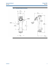
3.4.5 Sensor
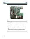
The sensor cable is pre-wired to a plug that inserts into a receiving socket on the signal board.
See Figures 3-1. The cable also passes through a strain relief fitting. To install the cable:
1. Remove the wrenching nut from the strain relief fitting.
2. Insert the plug through the hole in the bottom of the enclosure nearest the sensor socket.
Seat the fitting in the hole.
3. Slide the wrenching nut over the cable plug and screw it onto the fitting.
4. Loosen the cable nut so the cable slides easily.
5. Insert the plug into the appropriate receptacle. To remove the plug, squeeze the release
clip and pull straight out.
6. Adjust the cable slack in the enclosure and tighten the cable nut. Be sure to allow sufficient
slack to avoid placing stress on the cable and connections.
7. Plug the cable into the back of the sensor. The sensor is rated to IP65 when properly
connected to the cable. To prevent possible water damage to the connector contacts, be
sure the cable receptacle and the connector on the back of the sensor are dry when
connecting or disconnecting the cable.
8. Place the sensor in either the measuring chamber or the calibration cup. The sensor must
be in a dark place when power is first applied to the analyzer.
NOTE:
If “S1 Warning” appears, check sensor cable connection and confirm sample water
flow at debubbler drain outlet.
Wiring 13
Instruction Manual Clarity II T56
PN-51-T56 May 2012
RISK OF ELECTRICAL SHOCK
Electrical installation must be in accordance with the National Electrical Code
(ANSI/NFPA-70) and/or any other applicable national or local codes.
WARNING