


Section 3.0 Wiring
3.1 General
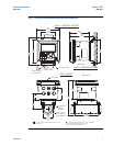
The T56 is easy to wire. It includes removable connectors and slide-out signal input boards. The
front panel is hinged at the bottom. The panel swings down for easy access to the wiring loca-
tions.
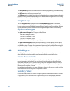
3.1.1. Removable connectors and signal input boards
The T56 uses removable signal input boards and communication boards for ease of wiring and
installation. Each of the signal input boards can be partially or completely removed from the
enclosure for wiring. The T56 has three slots for placement of up to two signal input boards and
one communication board
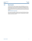
3.1.2. Signal input boards
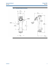
Slots 2 and 3 are for signal input measurement boards. Wire the sensor leads to the measurement
board following the lead locations marked on the board. After wiring the sensor leads to the signal
board, carefully slide the wired board fully into the enclosure slot and take up the excess sensor
cable through the cable gland. Tighten the cable gland nut to secure the cable and ensure a sealed
enclosure.
NOTE:
For the purpose of replacing factory-installed signal input boards, Rosemount Analytical Inc. is
the sole supplier.
3.1.3. Digital communication boards
HART digital communications is standard on the T56. A Profibus DP communication board is
available as an option for the T56 communication with a host. HART communications supports
Bell 202 digital communications over an analog 4-20mA current output. Profibus DP is an open
communications protocol which operates over a dedicated digital line to the host.
3.1.4 Alarm relays
Four alarm relays are supplied with the switching power supply (85 to 264VAC, -03 order code)
and the 24VDC power supply (20-30VDC, -02 order code). All relays can be used for process
measurement(s) or temperature. Any relay can be configured as a fault alarm instead of a process
alarm. Each relay can be configured independently and each can be programmed as an interval
timer, typically used to activate pumps or control valves. As process alarms, alarm logic (high or
low activation or USP*) and deadband are user-programmable. Customer-defined failsafe
operation is supported as a programmable menu function to allow all relays to be energized or
not-energized as a default condition upon powering the analyzer. The USP* alarm can be
programmed to activate when the conductivity is within a user-selectable percentage of the
limit. USP alarming is available only when a contacting conductivity measurement board is
installed.
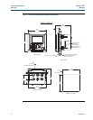
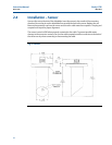
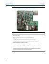
Slot 1-Left Slot 2 – Center Slot 3 – Right
Profi board Signal Board 1 Signal Board 2
Wiring 11
Instruction Manual Clarity II T56
PN-51-T56 May 2012