Reference Manual
00809-0100-4728, Rev KA
June 2011
Index-3
Rosemount 644
R
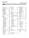
Recommended Actions . . . . . . . . 3-8
PlantWeb Alarms . . . . . . . . . . 3-8
RECOMMENDED_ACTION . . . . 3-8
Reference data . . . . . . . . . . . . .A-8
Reports . . . . . . . . . . . . . . . . . . . 3-5
Resource Block . . . . 3-4, 3-23, C-1
Block Errors . . . . . . . . . . . . . 3-23
Block Information . . . . . . . . . .C-1
Configuration . . . . . . . . . . . . . 3-4
Detailed Status . . . . . . . . . . . 3-23
FEATURES, FEATURES_SEL 3-5
Parameters . . . . . . . . . . . . . .C-2
BLOCK_ERR . . . . . . . . . . 3-23
Summary Status . . . . . . . . . . 3-23
Resource block . . . . . . . . . . . . .C-1
Return of Materials . . . . . . . . . . . 1-4
RTD
Ungrounded
. . . . . . . . . . . . . 2-11
Wiring . . . . . . . . . . . . . . . . . . 2-9
S
Security . . . . . . . . . . . . . . . . . . 3-5
Self Test . . . . . . . . . . . . . . . . . 3-24
Sensor
Connection
Diagram
. . . . . . . . . . . . . . 2-8
Millivolt . . . . . . . . . . . . . . . . . 2-8
Ohm . . . . . . . . . . . . . . . . . . . 2-9
RTD . . . . . . . . . . . . . . . . . . . 2-9
Thermocouple . . . . . . . . . . . . 2-8
Wiring . . . . . . . . . . . . . . . . . . 2-8
Sensor Calibration . . . . . . . . . . 3-18
Sensor Transducer Block . . 3-4, 3-9,
3-18, . . . . . . . . . . . . . . . . . . . .C-5
Block Information . . . . . . . . . .C-5
Configuration . . . . . . . . . . . . . 3-9
Operation and Maintenance . . 3-18
Parameters . . . . . . . . . . . . . .C-5
Simulate . . . . . . . . . . . . . . . . . 3-21
Simulation . . . . . . . . . . . . . . . . 3-21
Manual Mode . . . . . . . . . . . . 3-21
Soft W Lock, Hard W Lock . . . . . 3-5
Specifications
Performance
. . . . . . . . . . . . . A-3
Status . . . . . . . . . . . . . . . . . . . 3-21
AI block . . . . . . . . . . . . . . . . 3-13
STATUS_OPTIONS . . . . . . . . . 3-13
Supported Units . . . . . . . . . . . . 3-10
Switches
Simulate
. . . . . . . . . . . . . . . 3-21
T
Thermocouple
Grounded
. . . . . . . . . . . . . . 2-12
Ungrounded . . . . . . . . . . . . . 2-11
Wiring . . . . . . . . . . . . . . . . . . 2-8
Trim
Zero . . . . . . . . . . . . . . . . . . . 3-9
Troubleshooting . . . . . . . . . . . 3-16
Flowchart . . . . . . . . . . . . . . 3-16
LCD Transducer block . . . . . 3-24
Reference table . . . . . . . . . . 3-16
Resource Block . . . . . . . . . . 3-23
Types of Modes
Auto
. . . . . . . . . . . . . . . . . . . 3-2
Man . . . . . . . . . . . . . . . . . . . 3-2
Other Types of Modes . . . . . . 3-2
Out of Service . . . . . . . . . . . . 3-2
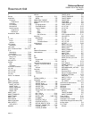
U
Uncertain
Limited . . . . . . . . . . . . . . . . 3-13
Man Mode . . . . . . . . . . . . . . 3-13
Unicode . . . . . . . . . . . . . . . . . . 3-5
UNITS_TYPE_# . . . . . . . . . . . 3-15
Upper Trim Method . . . . . . . . . 3-18
V
Virtual Communication Relationship
(VCRs) . . . . . . . . . . . . . . . . . . . 3-4
Network Parameters . . . . . . . . 3-4
W
Wiring . . . . . . . . . . . . . . . . . . . 2-7
Sensor Connection . . . . . . . . 2-8
Diagram . . . . . . . . . . . . . . 2-8
Millivolt . . . . . . . . . . . . . . . 2-8
Ohm . . . . . . . . . . . . . . . . . 2-9
RTD . . . . . . . . . . . . . . . . . 2-9
Thermocouple . . . . . . . . . . 2-8
X
XD_SCALE . . . . . . . . . . . . . . . 3-9
XD_SCALE, OUT_SCALE . . . . 3-10
L_TYPE
Direct
. . . . . . . . . . . . . . . 3-10
Z
Zero Trim . . . . . . . . . . . . . . . . . 3-9


