


Reference Manual
00809-0400-4728, Rev AA
June 2011
1-3
Rosemount 644
Refer to the following literature for a full range of compatible connection
heads, sensors, and thermowells provided by Emerson Process
Management.
• Temperature Sensors and Assemblies Product Data Sheet, Volume 1
(document number 00813-0100-2654)
• Temperature Sensors and Assemblies Product Data Sheet, Volume 2
(document number 00813-0200-2654)
CONSIDERATIONS
General Electrical temperature sensors such as RTDs and thermocouples produce
low-level signals proportional to their sensed temperature. The 644 converts
the low-level sensor signal to a standard 4–20 mA dc, or digital F
OUNDATION
fieldbus signal that is relatively insensitive to lead length and electrical noise.
This signal is then transmitted to the control room via two wires.
Commissioning The transmitter can be commissioned before or after installation. It may be
useful to commission it on the bench, before installation, to ensure proper
operation and to become familiar with its functionality. Make sure the
instruments in the loop are installed in accordance with intrinsically safe,
FISCO, or non-incendive field wiring practices.
Mechanical Location
When choosing an installation location and position, take into account the
need for access to the transmitter.
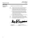
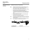
Special Mounting
Special mounting hardware is available for mounting a 644 head mount
transmitter to a DIN rail or assembling a new 644 head mount to an existing
threaded sensor connection head (former option code L1).
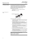
Electrical Proper electrical installation is necessary to prevent errors due to sensor lead
resistance and electrical noise. For best results, shielded cable should be
used in electrically noisy environments.
Make wiring connections through the cable entry in the side of the connection
head. Be sure to provide adequate clearance for cover removal.
Environmental The transmitter electronics module is permanently sealed within the housing,
resisting moisture and corrosive damage. Verify that the operating
atmosphere of the transmitter is consistent with the appropriate hazardous
locations certifications.
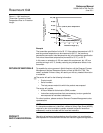
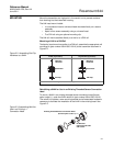
Temperature Effects
The transmitter will operate within specifications for ambient temperatures
between –40 and 185 °F (–40 and 85 °C). Heat from the process is
transferred from the thermowell to the transmitter housing. If the expected
process temperature is near or beyond specification limits, consider the use of
additional thermowell lagging, and extension nipple, or a remote mounting
configuration to isolate the transmitter from the process.
Figure 1-1 provides an example of the relationship between transmitter
housing temperature rise and extension length.