


Reference Manual
00809-0400-4728, Rev AA
June 2011
Rosemount 644
2-8
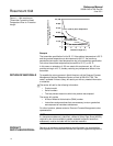
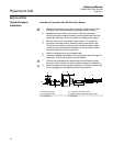
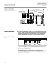
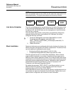
Figure 2-6. Connecting a
F
OUNDATION fieldbus Host
System to a Transmitter Loop
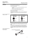
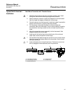
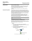
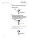
Sensor Connections The 644 is compatible with a number of RTD and thermocouple sensor types.
Figure 2-7 shows the correct input connections to the sensor terminals on the
transmitter. To ensure a proper sensor connection, anchor the sensor lead
wires into the appropriate compression terminals and tighten the screws.
Figure 2-7. Sensor Wiring
Diagrams
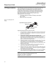
Thermocouple or Millivolt Inputs
The thermocouple can be connected directly to the transmitter. Use
appropriate thermocouple extension wire if mounting the transmitter remotely
from the sensor. Make millivolt inputs connections with copper wire. Use
shielding for long runs of wire.
Power
Supply
6234 ft (1900 m) max
(depending upon cable characteristics)
Integrated Power
Conditioner and Filter
Terminators
(Spur)
(Spur)
(Trunk)
(The power supply,
filter, first
terminator, and
configuration
tool are typically
located in the
control room.)
Devices 1
through 16
F
OUNDATION
fieldbus
Configuration
Tool
Power/
Signal
Wiring
644 Sensor Connections Diagram
* Emerson Process Management provides 4-wire sensors for all single element RTDs. Use these
RTDs in 3-wire configurations by leaving the unneeded leads disconnected and insulated with electrical
tape.
2-wire
RTD and ⍀
3-wire RTD
and ⍀
4-wire RTD
and ⍀
T/C
and mV
*
1234
1234
1234
1234