


Reference Manual
00809-0400-4728, Rev AA
June 2011
Rosemount 644
2-12
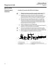
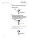
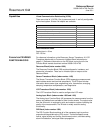
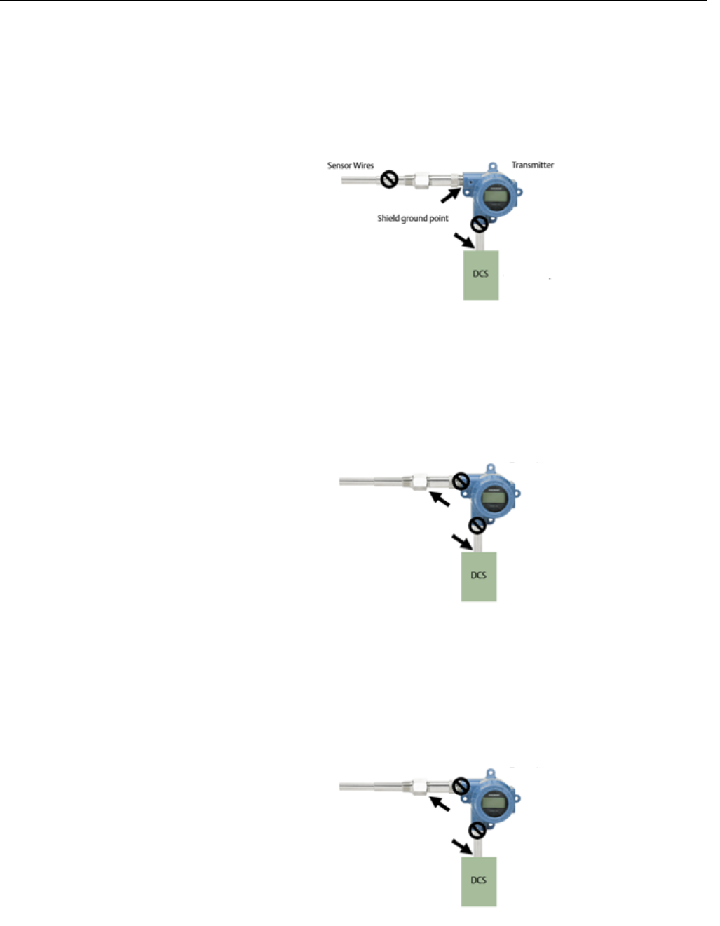
Option 2:
1. Connect sensor wiring shield to the transmitter housing (only if the
housing is grounded).
2. Ensure the sensor shield is electrically isolated from surrounding
fixtures that may be grounded.
3. Ground signal wiring shield at the power supply end.
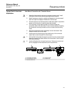
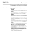
Option 3:
1. Ground sensor wiring shield at the sensor, if possible.
2. Ensure that the sensor wiring and signal wiring shields are electrically
isolated from the transmitter housing.
3. Do not connect the signal wiring shield to the sensor wiring shield.
4. Ground signal wiring shield at the power supply end.
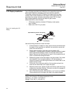
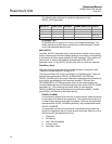
Grounded Thermocouple Inputs
1. Ground sensor wiring shield at the sensor.
2. Ensure that the sensor wiring and signal wiring shields are electrically
isolated from the transmitter housing.
3. Do not connect the signal wiring shield to the sensor wiring shield.
4. Ground signal wiring shield at the power supply end.
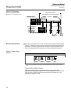
Transmitter
Shield ground point
Sensor Wires
FOUNDATION Fieldbus segment
Shield ground point
FOUNDATION Fieldbus segment
Transmitter
Sensor Wires
Shield ground point
FOUNDATION Fieldbus segment
Transmitter
Sensor Wires